background image


- 41 - 

              JUMBO NT


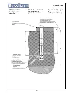
Bild 7 Die Fussabweiser werden auf 

dem Boden verdübelt. Der Abstand 

zwischen Auffahrschiene und 

Fußschutzblech beträgt ca. 10 mm. Die

Auffahrschiene darf, nach der 

Montage, nicht am Fußschutzblech 

streifen. 


9.4 Verlängerung der  

Hydraulikschläuche


•  Müssen gegebenenfalls die 

Hydraulikschläuche verlängert 
werden, muß anschließend geprüft 
werden, ob die Schläuche auch 
richtig zugeordnet wurden.  

Kontrolle: 

Annahme: Die Schläuche wurden 
richtig angeschlossen:  
Hebebühne auf ca. 500 mm 
hochfahren.  
Danach nur die Ausgleichs-
schraube A1 und die Notablaß-
schraube N1 am Bedienaggregat 
öffnen. 

Wirkung:

 Keine Seite der  

Hebebühne senkt sich ab. 
 

Annahme:

 Die Schläuche wurden  

nicht

 richtig angeschlossen:  

Hebebühne auf ca. 500 mm 
hochfahren.  
Danach die Ausgleichsschraube A1 
und die Notablaßschraube N1 am 
Bedienaggregat öffnen.


Wirkung:

 Eine Seite der  

Hebebühne senkt sich ab.  
Die Zuordnung der 
Hydraulikschläuche ist nochmals 
zu überprüfen.


•  Ausgleichsschraube A1 und die 

Notablaßschraube N1 wieder 
schließen.


Pic 7.The distance between the 

platform and the protection is approx. 

10 mm. The protection must not touch 

the platform. 


9.4  Extension of the hydraulics- 

hoses  

•  The hydraulics-hoses must be 

extended if necessary, must be 
tested afterwards, whether the 
hoses were also assigned right.  

Control:  

Assumption: the hoses was 
connected right:  
Raise the lift on approx. 500 mm.  
After it open the screw A1 
(equalisation) and the screw N1 
(emergency lowering) of the 
operating unit.  

Effect:  

no side of that  

lift subsides.


Assumption: the hoses became 


connected not right: 


Raise the lift on approx. 500 mm. 
After it open the screw A1 
(equalisation) and the screw N1 
(emergency lowering) of the 
operating unit. 

Effect: 

one side that


lift subsides.  
The assignment of the hydraulics-
hoses is to be checked again.  

•    Close the crew A1 and the crew  

N1again. 


Fig. 7 Monter la sécurité de pieds à 

côté du pont. D’abord amener le 

pont à la position basse. 

Positionner et cheviller la sécurité 

de pieds. Distance entre le chemin 

de roulement et la sécurité de pieds

env.  10 mm (La sécurité de pieds 

ne doit pas toucher le chemin de 

roulement).


9.5 Mise en service


 Avant las mise en service, il  

faut effectuer le contrôle de 
sécurité à caractère unique 
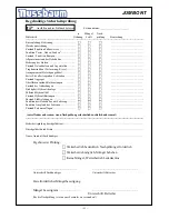
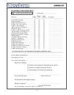
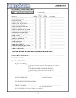
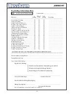
(utiliser le formulaire 
« contrôle de sécurité à 
caractère unique »). 


Si l’installation est réalisée par un 
spécialiste (monteur formé en usine), 
c’est ce dernier qui exécute ce 
contrôle. Si l’installation est effectuée 
par l’utilisateur, il faut alors charger 
un spécialiste d’exécuter le contrôle de 
sécurité. Ce dernier confirme le 
fonctionnement parfait du pont 
élévateur dans le protocole 
d’installation et dans le formulaire 
« contrôle de sécurité à caractère 
unique » et autorise le fonctionnement 
du pont élévateur. 
 

 Après la mise en service,  

veuillez remplir le protocole 
d’installation et le renvoyer au 
fabricant. 


Summary of Contents for Jumbo NT

Page 1: ...ruction and Documentation Notice d utilisation et carnet d inspection Seriennr serialno no de serie Otto Nu baum GmbH Co KG Korker Stra e 24 D 77694 Kehl Bodersweier Tel 49 0 7853 8990 Fax 49 0 7853 8...

Page 2: ...g instructions 24 5 1 Lifting the vehicle 24 5 2 Lowering the vehicle 25 5 3 Deaerate the cylinder 25 5 4 Equalisation the platform 28 6 Troubleshooting 30 6 1 Driving on an obstacle 31 6 2 Emergency...

Page 3: ...valid when not as agreed This is valid particularly for climb and go The Otto Nu baum Company is not liable for damages arising from this The user carries the risk alonely For the use belonged to obse...

Page 4: ...ed with the basic regulations concerning labour safety and accident prevention and being trained to operate the unit having read and understood the chapter concerning safety and warning instructions a...

Page 5: ...eile Teilausr stungen einhalten Diese T tigkeiten d rfen nur durch Sachkundige die an einer speziellen Werksschulung teilgenommen haben durchgef hrt werde to be controlled As far as required and order...

Page 6: ...to the lift manufacturer The copy remains in the manual Record of installation The automotive lift with the serial number was installed on at the firm at the safety was checked and the lift was start...

Page 7: ...7 Betriebsanleitung Stand 01 01 2010 date name of the competent person signature of the competent person Servicepartner Used safety dowels torque moments N Automotive lift date 06 2007 Manual date 01...

Page 8: ...was installed on at the firm at the safety was checked and the lift was started The persons below were introduced after the installation of the automotive lift The introduction was carried out from a...

Page 9: ...ger Unterschrift Sachkundiger Servicepartner date name signature date name signature date name signature date name of the competent signature of the competent Servicepartner date nom signature date no...

Page 10: ...of the automotive lift Only specialist staff is allowed to do work concerning safety and to do the safety checks of the lift They are called experts and competent person in this document Experts are p...

Page 11: ...ls danger This sign indicates danger to life Inexpert handling of the described operation may be dangerous to life caution This sign cautions against possible damage to the automotive lift or other ma...

Page 12: ...he max load distributation is 3 2 in or against drive on direction The automotive lift is only designed for servicing vehicles It is not allowed to carry persons with the lift It s not allowed to inst...

Page 13: ...achverst ndiger Ort Datum Unterschrift Sachverst ndiger 2 4 Displacement of the lift Displacement of the automotive lift expert checking resumption of work date kind of change signature of the compete...

Page 14: ...14 JUMBO NT 2 5 Konformit tserkl rung 2 5 attestation of conformity 2 5 D claration de conformit...

Page 15: ...ag Pay attention to the tension of your country 3 2 Safety device 1 Pressure relief valve Overprint safety of the hydraulic system 2 Holding valve safety device against unintentional lowering 3 Lockab...

Page 16: ...16 JUMBO NT 3 3 Datasheet 3 3 Fiche technique 3 3 Datenblatt...

Page 17: ...ou gauche l ordonnancement des tuyauterie est ex pliqu sur la fig Fondation des dalles Qualit du b ton min C20 25 Largeur min 2420 mm Longueur min 1660 mm Epaisseur min 160 mm Si le sol existant est...

Page 18: ...18 JUMBO NT...

Page 19: ...19 JUMBO NT...

Page 20: ...engrenage 0 4 Filtre aspirateur 0 5 Jauge de niveau d huile 0 6 Limiteur de pression 0 7 Clapet anti retour 0 8 Clapets anti retour pilot s 0 9 Vis d vacuation d urgence 0 10 Vis d quilibrage 0 11 Ro...

Page 21: ...floor Pos Description piece Lift 1 reduction 8 6 4x 2 T piece NW8 2x 3 hydraulic tube 450 mm 4x 4 hydraulic tube 3400 mm 1x 5 hydraulic tube 3400 mm 1x 6 hydraulic tube 850 mm 2x 7 hydraulic tube 1500...

Page 22: ...ent where the operating unit stands Le positionnement du pupitre de commande peut se faire droite ou bien gauche du pont l vateur Les tuyaux sont position selon plan 1500 mm 2x 8 Schlauch 2SCNW6 2x ge...

Page 23: ...ars old are to operate this lift During lifting or lowering the vehicle it must be observed from the operator Position the polymer supports as described of the vehicle manufacturer under the vehicle I...

Page 24: ...the wheelbase is too short and the wheels are standing on the ramps remove the ramps Block the vehicle against rolling put into gear Position elastomer supports under the pick up points of the vehicl...

Page 25: ...s den gesamten Senkvorgang beobachten Befindet sich das Fahrzeug in der untersten Position sind die Polymerauflagen zu entfernen und das Fahrzeug ist von der Hebeb hne zu fahren 5 3 Entl ften des Hydr...

Page 26: ...eraus Ungleichlauf etc Richtiges Entl ften Es ist sicherzustellen dass ca 14 Liter Hydraulik l eingef llt sind Die Hebeb hne ohne Last in die oberste Endposition fahren Die vordere rechte und die vord...

Page 27: ...l ftungsschrauben wieder verschlie en ansonsten kann es zu Fehlfunktionen der Hebeb hne kommen Die Hebeb hne durch dr cken des Heben Tasters erneut in die obere Endposition fahren Ausgleichsschrauben...

Page 28: ...t If it is sure there is no leak in the hydraulics system and no other external fault a compensation may be carried out Lower the lift in the lowest position Drive the vehicle from the lift If necessa...

Page 29: ...langsam ge ffnet wird Durch diesen Vorgang wird die Hebeb hne im untersten Bereich ausgeglichen was weitere folgende Massnahmen erfordert Die Ausgleichsschrauben A1 und A2 sind wieder zu verschlie en...

Page 30: ...lastic cover 6 Troubleshooting If the lift does not work properly the reason for this might be quite simple Please check the lift for the potential reasons mentioned on the following pages If the caus...

Page 31: ...Dabei ist der Taster Heben solange zu dr cken bis das Hindernis entfernt werden kann 6 2 Notabla der Hebeb hne Ein Notabla ist ein Eingriff in die Steuerung der Hebeb hne und darf nur von erfahrenen S...

Page 32: ...es of the lift and be sure that there are no objects or people in the immediate area of the lift or on the lift Before the emergency lowering process loose the electrical power supply Loose and remove...

Page 33: ...achten Danach sind die Polymerauflagen zu entfernen und das Fahrzeug ist von der Hebeb hne zu fahren Nach Beendigung des Notablasses sind die Notabla schrauben N1 und N2 zu verschlie en und wieder zu...

Page 34: ...ndards of the countries in which we sale European regulations for instance oblige inspection by qualified personnel every 12 months during the life span of the lift Whatever the regulations are in a g...

Page 35: ...ettoyage du pont levateur Un nettoyage p riodique est n cessaire au bon fonctionnement du pont l vateur afin d liminer toute l ments voir ci dessous pouvant amener d t rioration sel sable caillou sale...

Page 36: ...during the life time of the lift Proper maintenance records should be kept to back up possible warranty claims 7 2 Cleaning the Lift A regular and appropriate maintenance served the preservation of th...

Page 37: ...Il est recommand d ex cuter en m me temps une maintenance Apr s modifications de la construction par exemple modification de la limite de charge ou la r duction de la course de levage et apr s des re...

Page 38: ...de s rie ne doit pas tre install e dans des locaux atmosph re explosive ou dans des halles de lavage Avant la mise en place du pont l vateur il faut justifier de fondations suffisantes ou r aliser cel...

Page 39: ...acuation d air au bout des v rins s quences contr ler le bon parall lisme du pont percer les trous pour mise en place des chevilles en prenant soin de d poussi re avant la mise en place des chevilles...

Page 40: ...ise and lower the lift several times with load Check the torque of the dowels and check the hydraulic parts for tightness If necessary equalize the lift again read the chapter 5 5 Mount the covers Dow...

Page 41: ...on the hoses was connected right Raise the lift on approx 500 mm After it open the screw A1 equalisation and the screw N1 emergency lowering of the operating unit Effect no side of that lift subsides...

Page 42: ...fixation des planchers et de la colonne de commande Faire descendre le pont la position basse D brancher l alimentation lectrique D brancher la tuyauterie hydraulique si possible au pupitre de comman...

Page 43: ...transportieren Aufbauen der Hebeb hne entsprechend der Vorgehensweise beim Aufstellen und Verd beln vor der ersten Inbetriebnahme Es sind neue D bel zu verwenden Die alten D bel sind nicht mehr verwe...

Page 44: ...44 JUMBO NT Bild 17 Auswahl der D bell ngen ohne Bodenbelag Pic 17 choice of the dowel length without floor pavement or tile surface Fig 17 Choix de la longueur des chevilles sans rev tement...

Page 45: ...45 JUMBO NT Bild 18 Auswahl der D bell ngen mit Bodenbelag Pic 18 choice of the dowel lenght with floor pavement or tile surface Fig 18 Choix de la longueur des chevilles avec rev tement...

Page 46: ...n 140mm Diameter of bore d 15 mm Thickness of the lift pieces e 0 40mm Number of dowels 12 piece Starting torque 40 Nm Tableau relatif la fig 17 Cheville Liebig Type de cheville BM10 15 70 40 Profonde...

Page 47: ...Diameter of bore d 15 15 15 Thickness of the lift pieces e 40 65 65 100 100 140 Number of dowels 12 12 12 Quality of concrete min C20 25 normal bewehrt Starting torque 40Nm 40Nm 40Nm Tableau relatif l...

Page 48: ...fl chenzustand Kolbenstangen F F F Zustand der Abdeckungen F F F Dichtigkeit Hydraulikanlage F F F F llstand Hydraulik l F F F Zustand Hydraulikleitungen F F F Zustand Elektroleitungen F F F Funktions...

Page 49: ...stand Kolbenstangen F F F Zustand der Abdeckungen F F F Dichtigkeit Hydraulikanlage F F F F llstand Hydraulik l F F F Zustand Hydraulikleitungen F F F Zustand Elektroleitungen F F F Funktionstest Hebe...

Page 50: ...stand Kolbenstangen F F F Zustand der Abdeckungen F F F Dichtigkeit Hydraulikanlage F F F F llstand Hydraulik l F F F Zustand Hydraulikleitungen F F F Zustand Elektroleitungen F F F Funktionstest Hebe...

Page 51: ...stand Kolbenstangen F F F Zustand der Abdeckungen F F F Dichtigkeit Hydraulikanlage F F F F llstand Hydraulik l F F F Zustand Hydraulikleitungen F F F Zustand Elektroleitungen F F F Funktionstest Hebe...

Page 52: ...stand Kolbenstangen F F F Zustand der Abdeckungen F F F Dichtigkeit Hydraulikanlage F F F F llstand Hydraulik l F F F Zustand Hydraulikleitungen F F F Zustand Elektroleitungen F F F Funktionstest Hebe...

Page 53: ...stand Kolbenstangen F F F Zustand der Abdeckungen F F F Dichtigkeit Hydraulikanlage F F F F llstand Hydraulik l F F F Zustand Hydraulikleitungen F F F Zustand Elektroleitungen F F F Funktionstest Hebe...

Page 54: ...stand Kolbenstangen F F F Zustand der Abdeckungen F F F Dichtigkeit Hydraulikanlage F F F F llstand Hydraulik l F F F Zustand Hydraulikleitungen F F F Zustand Elektroleitungen F F F Funktionstest Hebe...

Page 55: ...nzustand Kolbenstangen F F F Zustand der Abdeckungen F F F Dichtigkeit Hydraulikanlage F F F F llstand Hydraulik l F F F Zustand Hydraulikleitungen F F F Zustand Elektroleitungen F F F Funktionstest H...

Page 56: ...Fixed seat of the screws F F F Condition operating unit F F F Condition surface piston rod F F F Condition coverings F F F Condition electrical wires F F F Level of hydraulic oil F F F Condition of th...

Page 57: ...t of the screws F F F Condition operating unit F F F Condition surface piston rod F F F Condition coverings F F F Condition electrical wires F F F Level of hydraulic oil F F F Condition of the hydraul...

Page 58: ...t of the screws F F F Condition operating unit F F F Condition surface piston rod F F F Condition coverings F F F Condition electrical wires F F F Level of hydraulic oil F F F Condition of the hydraul...

Page 59: ...t of the screws F F F Condition operating unit F F F Condition surface piston rod F F F Condition coverings F F F Condition electrical wires F F F Level of hydraulic oil F F F Condition of the hydraul...

Page 60: ...t of the screws F F F Condition operating unit F F F Condition surface piston rod F F F Condition coverings F F F Condition electrical wires F F F Level of hydraulic oil F F F Condition of the hydraul...

Page 61: ...t of the screws F F F Condition operating unit F F F Condition surface piston rod F F F Condition coverings F F F Condition electrical wires F F F Level of hydraulic oil F F F Condition of the hydraul...

Page 62: ...t of the screws F F F Condition operating unit F F F Condition surface piston rod F F F Condition coverings F F F Condition electrical wires F F F Level of hydraulic oil F F F Condition of the hydraul...

Page 63: ...t of the screws F F F Condition operating unit F F F Condition surface piston rod F F F Condition coverings F F F Condition electrical wires F F F Level of hydraulic oil F F F Condition of the hydraul...

Page 64: ...t of the screws F F F Condition operating unit F F F Condition surface piston rod F F F Condition coverings F F F Condition electrical wires F F F Level of hydraulic oil F F F Condition of the hydraul...

Page 65: ...seat of the screws F F F Condition operating unit F F F Condition surface piston rod F F F Condition coverings F F F Condition electrical wires F F F Level of hydraulic oil F F F Condition of the hydr...

Page 66: ...des pistons F F F Etat couvercles F F F Etanch it circuit hydraulique F F F Niveau huile hydraulique F F F Etat conduites hydrauliques F F F Etat conduites lectriques F F F Test de fonctionnement ave...

Page 67: ...F F F Etat couvercles F F F Etanch it circuit hydraulique F F F Niveau huile hydraulique F F F Etat conduites hydrauliques F F F Etat conduites lectriques F F F Test de fonctionnement avec v hicule F...

Page 68: ...F F F Etat couvercles F F F Etanch it circuit hydraulique F F F Niveau huile hydraulique F F F Etat conduites hydrauliques F F F Etat conduites lectriques F F F Test de fonctionnement avec v hicule F...

Page 69: ...F F F Etat couvercles F F F Etanch it circuit hydraulique F F F Niveau huile hydraulique F F F Etat conduites hydrauliques F F F Etat conduites lectriques F F F Test de fonctionnement avec v hicule F...

Page 70: ...F F F Etat couvercles F F F Etanch it circuit hydraulique F F F Niveau huile hydraulique F F F Etat conduites hydrauliques F F F Etat conduites lectriques F F F Test de fonctionnement avec v hicule F...

Page 71: ...F F F Etat couvercles F F F Etanch it circuit hydraulique F F F Niveau huile hydraulique F F F Etat conduites hydrauliques F F F Etat conduites lectriques F F F Test de fonctionnement avec v hicule F...

Page 72: ...F F F Etat couvercles F F F Etanch it circuit hydraulique F F F Niveau huile hydraulique F F F Etat conduites hydrauliques F F F Etat conduites lectriques F F F Test de fonctionnement avec v hicule F...

Page 73: ...F F F Etat couvercles F F F Etanch it circuit hydraulique F F F Niveau huile hydraulique F F F Etat conduites hydrauliques F F F Etat conduites lectriques F F F Test de fonctionnement avec v hicule F...

Page 74: ...F F F Etat couvercles F F F Etanch it circuit hydraulique F F F Niveau huile hydraulique F F F Etat conduites hydrauliques F F F Etat conduites lectriques F F F Test de fonctionnement avec v hicule F...

Page 75: ...ns F F F Etat couvercles F F F Etanch it circuit hydraulique F F F Niveau huile hydraulique F F F Etat conduites hydrauliques F F F Etat conduites lectriques F F F Test de fonctionnement avec v hicule...

Page 76: ...0 7853 8787 SCHALTPLAN OBJEKT ANLAGE KUNDE worden halten bitten wir Der Schaltschrank wurde unter Beachtung der anerkannten Regeln der Technik nach nach VDE0100g 7 75 Par 22 Vor Inbetriebnahme Verdrah...

Page 77: ...m Datum Bl Nussbaum Hebetechnik GmbH Co KG D 77694 Kehl Bodersweier Tel 49 0 7853 899 0 Fax 49 0 7853 8787 Inhaltsverzeichnis JUMBO NT Boe Blatt 2 von 6 001 Deckblatt 002 Inhaltsverzeichnis 003 004 St...

Page 78: ...1 4 3 PE X0 400 V 50Hz 230V 55VA 1 2 3 4 T1 TR1 TR2 KM1 S0 JUMBO NT Boe Blatt 3 von 6 16A Sicherung Bauseits Fxx main switch Commutateur principal fuse by customer fusible vous incombant 3 X 16 A T b...

Page 79: ...b fahren A1 A2 K3 4 bei Fotozelle vorhanden CE Stop Connexion absence CE Stop Connexion en magasin with CE Stop absence with photocell absence with photocell existing with CE Stop existing JUMBO NT Bo...

Page 80: ...0334 Marquardt S2 1 990321 PVC KAPPE Marquardt 12 1 990249 Reflektionslichtschranke 24 240V AC Telemecanique S3 13 1 990003 Bernstein S4 14 1 990659 Trenntransformator 1 ph 230V 230V 55VA Schmelzer T1...

Page 81: ...iv klemme D 6 8 ADO grau schraub schn Entrelec Schiele X0 20 1 990578 Schutzleiterkl D 1 5 6 P ADO GR GE schn schn Entrelec Schiele X2 1 981393 Ventilspule 200V DC 100 ED Jung Gmbh Y1 1 981393 Ventils...

Page 82: ...Hebel sind Die Beweglichkeit des Hebels ist danach zu pr fen If necessary adjust the clamping sleeve and check the function of the lever Les goupilles lastiques doivent ventuellement tre raccord es af...

Reviews: