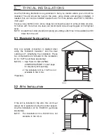
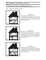
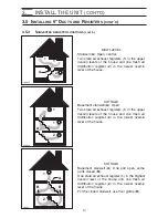
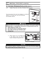
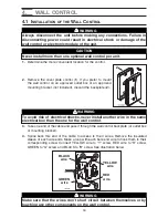
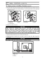

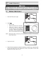

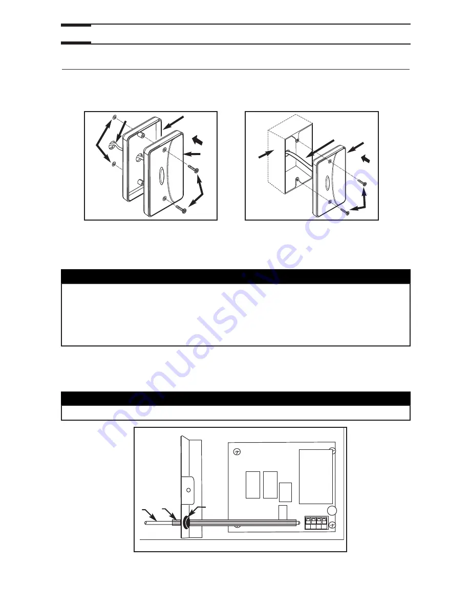
5.
Pass the other end of the cable through the wall. Reinstall the cover plate. Using wall
anchors (not included) and provided screws, mount the wall control on the wall. See
illustrations below.
1) Wall anchors
4) Control
1) Outlet box
3
) Control
2) Control cable
5) Screws
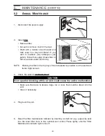
2) Control cable
4) Screws
3
) Control backplate
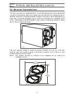
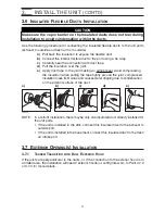
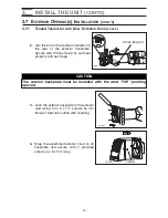
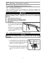
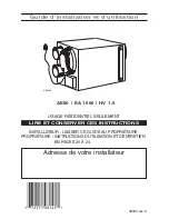
6.
Route the cable to the unit.
7.
Remove the electrical box cover on the side of the unit.
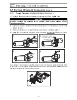
8.
Slide the sleeve (included) over the cable control and pass the cable through the
grommet.
1) Cable control
2) Sleeve
3
) Grommet
4.
WALL CONTROL
(CONT’D)
4.1 I
NSTALLATION OF THE
W
ALL
C
ONTROL
(
CONT
’
D
)
19
VC0052
VC0051
1
2
3
4
5
2
3
4
1
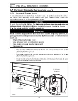
CAUTION
Keep control low voltage wiring at least 1 foot (305 mm) away from
motors, lightning ballast, light dimming circuit and power distribution
panel. Do not route control wiring along with house power wiring. Avoid
poor wiring connections. Failure to follow these practices can introduce
electrical interference, which can cause erratic control operations.
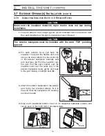
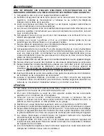
CAUTION
The sleeve must stay in the grommet. See figure below.
VD0157
1
2
3


