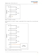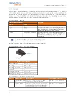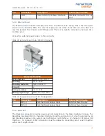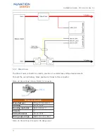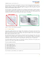
If reducing the cable length is not feasible or if there is no time to physically modify the lengths, a
common solution is to wrap the excess cable length in a coil and fasten the wire loop in the
cabinet. This basic tactic has the undesirable effect of creating an air-core transformer which will
couple EMI into the cable extremely well.
The best solution to cable length management is to bundle the excess length in a figure-8 pattern.
This prevents the bundle from turning into an air-core transformer since the direction of current in
one side of the figure-8 turns opposite to the current in the other side. It is recommended to use
the figure-8 method if physically reducing the cable length is not possible.
Figure 15. Excess Cable Management Examples
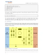
6.3. System Noise
High-power inverters generate a lot of system noise, especially on the DC bus. This is due to the
industry standards for AC harmonics and EMC on the grid-side which require the DC bus to help
filter out the harmful emissions. Unfortunately, that means the battery cells, and the Nuvation
BMS, experience extreme levels of noise.
The most harmful emissions on the DC bus are between the DC bus and earth. This is due to the
slew-rate of the switching devices implemented in the inverter (usually IGBTs). The slew-rate is
impacted by a many elements, and the emissions can be minimized by carefully grounding the
installation so that the return-path for the high-frequency switching noise can be kept small.
The Nuvation BMS has various faults and informative registers to determine if the system has a
high level of noise that is impacting the Nuvation BMS.
The communication faults are:
sc_fault_linkbus_wdt.trig
sc_fault_stackbus_rxwdt.trig
sc_fault_stackbus_txwdt.trig
sc_fault_pi_afe_wdt.trig
sc_fault_controller_wdt.trig
The informative communication error registers are:
Installation Guide - 2018-10-08, Rev. 2.0
34


