17
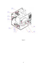
5.16. Replacing Locking Bobbin ( see Figure 7 & Figure 9)
•
Remove the flywheel handles (4).
•
Remove the lid protection cover (3) by removing its 4 screws.
•
Take the locking bobbin out by removing the bobbin (14) connection screws.
•
Separate the locking bobbin (14) electrical connection cables by cutting their welding points.
•
Take the pin on the locking bobbin and fix it onto the new bobbin.
•
Mount the new bobbin.
•
Connect the electrical connection cables by welding them carefully.
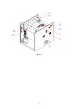
5.17. Replacing Locking Switch ( see figure 10)
•
Disconnect the locking switch (30) terminal connections.
•
Take the locking switch out by removing the locking switch connection nuts.
•
Mount the new locking switch and make the necessary electrical connections carefully according to
the electrical circuit diagram (figure 3 or Figure 4).
•
Adjust the switching length carefully.
5.18. Cleaning The Sterilizatior Chamber Filter ( see Figure 8 & Figure 11)
•
Take the shelf carrier (12) and the heater protection sheet (11) out by removing the shelf carrier
mounting screws (34) in the sterilization chamber.
•
Take the filter (36) out which is placed on the bottom of the chamber by removing the water inlet
record (35) with a wrench.
•
Clean the filter pores and re-mount it.
5.19. Replacing Pressure Switch ( see Figure 10)
•
Disconnect the cable connections of pressure switch terminals
•
Remove the pressure switch
•
Put some liquid gasket to female connectors of the new pressure switch to ensure that there is no
leakage and mount the new pressure switch
•
Make the electrical connections carefully according to the electrical circuit diagram (Figure 3 or
Figure 4)
•
Adjust the minimum pressure switch (33) by turning the red adjusting switch counter-clockwise or
adjust the maximum pressure switch (32) by turning the red adjusting switch clockwise.
Summary of Contents for OT 020
Page 19: ...18 SECTION 6 DIAGRAMS AND DRAWINGS ...
Page 20: ...19 6 1 ELECTRICAL CIRCUIT DIAGRAM OT 020 Figure 3 ...
Page 21: ...20 6 2 ELECTRICAL CIRCUIT DIAGRAM OT 020V Figure 4 ...
Page 22: ...21 6 3 WATER AND STEAM UNIT DIAGRAMS Figure 5 OT 020 flow diagram ...
Page 23: ...22 Figure 6 OT 020V flow diagram ...
Page 24: ...23 SECTION 7 SPARE PART LIST ...
Page 25: ...24 Figure 7 ...
Page 26: ...25 Figure 8 ...
Page 27: ...26 Figure 9 ...
Page 28: ...27 Figure 10 ...
Page 29: ...28 Figure 11 ...

