8
SECTION 3
SERVICING
Caution: Before servicing the instrument, please take the necessary precautions for your
health. Please respect to the warnings on the unit!!
Please make sure that you have disconnected the unit before you service it.
3
.1. GENERAL OVERVIEW
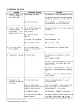
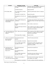
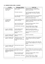
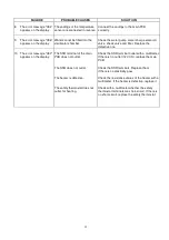
The failures can be diagnosed according to the following tables.
Most of the arising problems can be determined by the help of a multimeter.
The components on the main PCB must not be replaced even the failure is caused by one of the
components on the main PCB. In this case, please send the failed PCB to factory service along with a
note on which the failure explanations are written.
Before replacing the PCB or any control element, please make sure that the failure is not caused by
weak wire and terminal connections.
Summary of Contents for OT 020
Page 19: ...18 SECTION 6 DIAGRAMS AND DRAWINGS ...
Page 20: ...19 6 1 ELECTRICAL CIRCUIT DIAGRAM OT 020 Figure 3 ...
Page 21: ...20 6 2 ELECTRICAL CIRCUIT DIAGRAM OT 020V Figure 4 ...
Page 22: ...21 6 3 WATER AND STEAM UNIT DIAGRAMS Figure 5 OT 020 flow diagram ...
Page 23: ...22 Figure 6 OT 020V flow diagram ...
Page 24: ...23 SECTION 7 SPARE PART LIST ...
Page 25: ...24 Figure 7 ...
Page 26: ...25 Figure 8 ...
Page 27: ...26 Figure 9 ...
Page 28: ...27 Figure 10 ...
Page 29: ...28 Figure 11 ...


