background image

13

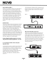
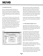
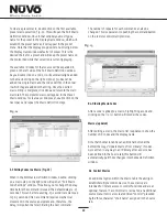
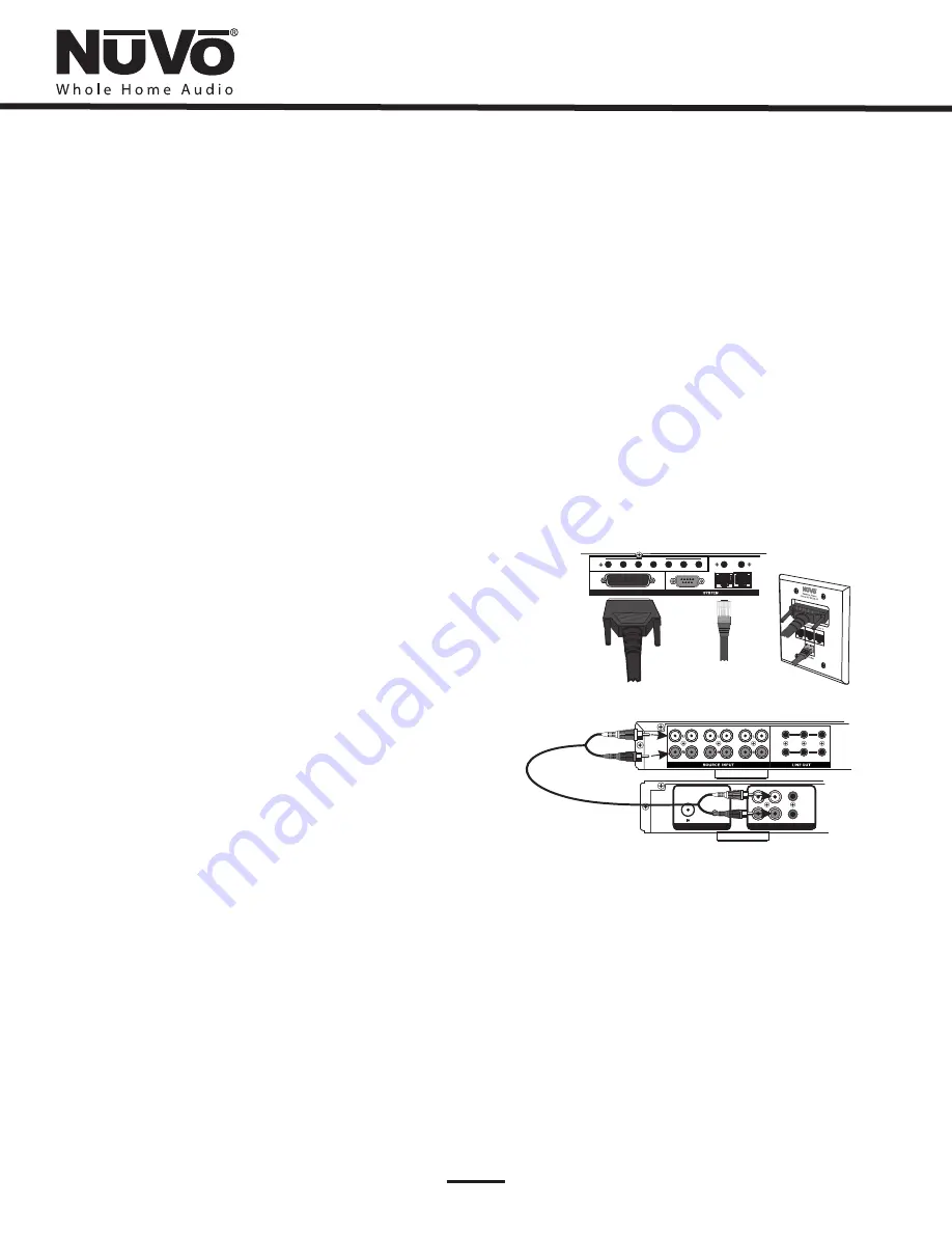
V. Connecting the Allport to the Essentia Amplifier (Fig. 4)

The

fig. 4 diagram shows the connection to the NV-E6MAP-DC
Allport.

Once installed, the front of the Allport has three

Device

RJ45 jacks for CAT5 connections from the NuVoNet Suite
components, and an RJ45 jack labeled

NuVoNet

which

must be connected to the

NuVoNet

input on the back of

the Essentia amplifier. This is necessary for Control Pad
communication, regardless the use of the NuVoNet Suite
components. Once connected, the Control Pads are ready to
communicate with the System. The Essentia System is
shipped with a six-foot pre-terminated CAT5 network cable,
or you can purchase one if a different length is required.

The speaker connection is made with the 25-pin Allport
Cable. The modular speaker connectors must be plugged into
the appropriate speaker connections on the back of the
Allport.

Fig. 4

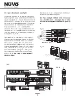
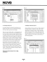
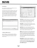
VI. Attaching Audio Source Equipment (Fig. 5)

Each piece of audio equipment is connected to the Essentia
amplifier with standard stereo RCA cables. Attach an RCA
cable to the corresponding audio output on the source
equipment and to the desired source input on the back of
the Essentia amplifier. The numbered input for each source
is important in the configuration of the system. This will be
covered in detail in the Essentia Configurator portion of this
manual.

The Zone 1 and 2 outputs have 3.5mm stereo pre-amp
lineouts attached to them. Their purpose is to provide the
zone

s current audio selection signal to an additional

amplifier. Both versions, fixed (a constant signal that
requires a volume control separate from the NuVo zone
Control Pad) and variable (a signal that varies in level
relative to the volume setting on the NuVo zone Control Pad)
are both simultaneously active and require no external
switch for use.

Each output has an attached voltage trigger output that
allows the attached amplifier to be triggered from a voltage
presented when the zone Control Pad is turned on. The
voltage trigger is removed when the zone is turned off.

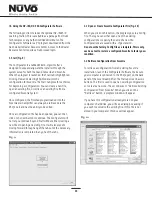
Using the Fixed and Variable Lineouts

Fig. 5

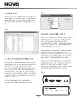
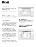
T2 AM/FM Tuners

Unitialized State

Detected (Press OK)

OK

Tuner A, Standalone, Source 1, Source 2,

Source 3, Source 4, Source 5,

Source 6.

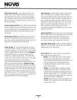
Each of the T2 Tuner components houses two individual
AM/FM receivers, which have their own display on the front
panel. Once the T2 is plugged in and the NuVoNet CAT5 is
connected to the Allport, the initial display,

will appear. When the

button is

touched, the Tuner will prompt a regional tuning selection. It
will then go to

and

Stand Alone is

automatically highlighted at initial startup. Use the arrows
to scroll to the appropriate source number. When the
selection is made, the T2 will go to the same selection for
Tuner B. When each output selection is complete, the
Essentia System NuVoNet will recognize that source.

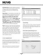
Setting up NuVo Sources for use with NuVoNet

IX. Using the Essentia Configurator

Software

.

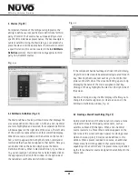
A feature of the Essentia System is its ability to
automatically communicate with the T2 Tuners, Music Port,
and the NuVoDocks for iPod. The communication happens
through the Allport connection hub across a communication
protocol called NuVoNet. Although software programming is
not necessary for this function, configuring the installation
through the Configurator Software prior to installation has
distinct advantages, see

, page 16

When the T2 Tuners are plugged in for the first time, they
will display a prompt to select a source input number for the
Essentia. For NuVoNet to communicate properly, you should
have already connected the NuVoNet components to one of
the three

Peripheral Device

inputs on the face of the

Allport.

STATUS

NuVoNet

RS232

1

SUM

ALLPORT CONNECTION

IR OUTPUTS

2

3

4

5

6

LINK

MUTE

ALLPORT CONNECTION

IN

L

R

FIXED

VAR

ZONE

1

TRIG

ZONE

2

1

2

3

4

5

6

USE ONLY NuVo

NV-T2PAS

POWERED ANTENNA SYSTEM

AUDIO OUT

AUX IN

TRIGGER
ON=+12V

AUDIO

OUTPUT

ANTENNA INPUT

TUNER B

Summary of Contents for Essentia NV-E6GMS-UK

Page 1: ...Installation Guide Essentia NV E6GMS DC NV E6GMS UK...

Page 2: ......

Page 3: ...closure that will impede the flow of cooling air 8 Do not install this product near any heat sources such as radiators heat registers stove or other apparatus including heat producing amplifiers that...

Page 4: ...r s d eau comme par exemple baignoires viers piscine sous sol humides Etc e cela Prot ger pincement particuli rement au niveau des fiches des r ceptacles utilis s et l endroit de sortie de l appareil...

Page 5: ...15 IX Using the NV I8G NV E6G Configurator Software 1 Start Page 16 2 IR Libraries Page 17 Page 20 4 Macros Page 21 5 Zones Page 23 6 System Settings Page 25 7 Download Update Page 27 X Control Pad Se...

Page 6: ...g less than 1 watt of power when used with the single gang OLED Control Pads Even with all the zones turned on and in full operation the efficient design results in low power consumption Essentia trul...

Page 7: ...device It is also used for configuration programming download 8 This is a constant 5 volt output for triggering external equipment There is no voltage output when the zones are off 9 This RJ45 connect...

Page 8: ...ific zone and system setting parameters 8 This IR programmable button toggles between the play and pause functions of the chosen source When using the T2 Tuners this button toggles through the Tuner s...

Page 9: ...gles through the Tuner s receive modes A third press and hold function can also be assigned to this button for additional functionality 9 The OK button serves a dual function In normal play mode it sc...

Page 10: ...ss to music browsing presets and favorites as well as specific zone setting parameters 8 9 The OK button also serves a dual function In normal play mode it scrolls through the available audio sources...

Page 11: ...features 8 This icon indicates that the zone is set for Do Not Disturb There are three Do Not Disturb choices exclude the zone from Party Mode Page Mode and or System Mute 9 This icon will light when...

Page 12: ...nes is listed on the display The user can change zone control by moving the highlight to the desired zone and pressing the OK button 9 The OK button serves a dual function In normal play mode it seque...

Page 13: ...tes buttons 6 This button allows access to the Display menu available at each Control Pad 7 This LED Light Emitting Diode lights to indicate a button push 8 The GRC1 remote provides a discrete mute fu...

Page 14: ...r and trim them evenly across the top Most crimp tools have a wire trimmer built in It is best to trim the wires to about in length 4 While holding the wires flat between your thumb and forefinger ins...

Page 15: ...llport can be installed Section VIII Expanding Essentia to 12 Zones Section II Terminating the Speaker Wire Fig 2 III Installing the Essentia Amplifier System setup works best when the amplifier is pl...

Page 16: ...at allows the attached amplifier to be triggered from a voltage presented when the zone Control Pad is turned on The voltage trigger is removed when the zone is turned off Using the Fixed and Variable...

Page 17: ...red NuVoDocks could be used as individual sources through NuVoNet The NuVoDocks consist of a dock for iPod playback and recharging as well as a receiver component designed to communicate with NuVoNet...

Page 18: ...nd the additional zone speakers A second Allport cable must be attached from the expander Allport to the expander amplifier and a short CAT5 jumper cable included with the expander system is used on t...

Page 19: ...et you continue beyond Start without either creating a new file or opening an existing file It will also prevent moving forward through any of the tabs until the necessary information is completed in...

Page 20: ...the IR Learning Station Package Capturing function codes and adding them to the component IR Library is an easy process The Interface box is connected to your computer using one of the RS232 connectio...

Page 21: ...cessary to record the IR codes associated with each function To do this connect the Learning Station Interface as described above Double click on the desired component from the IR Library page This wi...

Page 22: ...ond appropriately to the command if it has been stored correctly A test result box will open where you can record yes or no to the test Three successful test results are required before the Passed cou...

Page 23: ...between sources relative volume levels remain constant When the appropriate information is complete click OK This will add the updated source information to the Source window When all the desired sou...

Page 24: ...he macro on the right side of the screen Double clicking on a key in either display will allow you to change the default assignment or create a new one in the Edit Macro Definitions window Fig 21 4 Ma...

Page 25: ...drop down menu directly below the Display Name window defaults to Forever This is the desired choice for a preset and will keep the preset name on the Control Pad while that selection is currently pla...

Page 26: ...speakers or simply to prevent a certain room from being turned up too high e g a teenager s bedroom This controls the reset volume level for each zone when the All On Party Mode is initiated from any...

Page 27: ...rol s commands from being received by the Control Pad and passed through to the source equipment Volume Reset at Zone ON Loudness Compensation ON Exclusive Source Control A zone specific feature is th...

Page 28: ...ontrol Pads This is a useful feature for large rooms where more than one Control Pad is desired If slave Control Pads are used we suggest that you disable the IR pass through on those to prevent cross...

Page 29: ...elay Fig 29 In this mode a single tap of the power button turns the zone off and holding the power button causes a second menu that gives the option to turn off that zone s group or turn all the zones...

Page 30: ...re version If they are at a lesser version number an upgrade notice will appear on the display It is important to allow this process to complete When the Control Pad is finished upgrading itself it wi...

Page 31: ...e grayed out That specific zone will have a check mark displayed Any available addresses will be accessible Scrolling to will erase the current address XI Using the Control Pad s MENU Button MAIN MENU...

Page 32: ...ll Off command is issued from a Control Pad Fig 37 Party Mode Do Not Disturb Sleep Mode This setting is turned on and off with the OK button When selected all the configured zones in the system will t...

Page 33: ...are defined in the next section Fig 40 Favorites 1 12 Twelve global favorites can be defined for easy access from within the Main Menu or from the twelve numeric favorites from the Essentia remote co...

Page 34: ...l on function is initiated Balance Bass Treble Loudness Compensation Volume Settings Volume Reset Initial Volume Maximum Volume Page Volume Party Volume Fig 43 Fig 44 Fig 45 Advanced Zone Settings The...

Page 35: ...by scrolling to the desired zone and selecting it All used zone addresses will be grayed out If you have defined zones in the Configurator Software the actual zone names assigned in the Zone tab of t...

Page 36: ...o output for paging that is plugged into source input 6 on the Essentia note that this feature eliminates the use of Source 6 as an audio source for the system To use the Page function you must select...

Page 37: ...D 4 IR EMITTER 5 IR BLASTER A standard 12 volt power supply is included in the Learning Station Package This will supply the necessary AC power for IR learning and testing Using one of the supplied R...

Page 38: ...new equipment codes the Learning Station Interface box must be connected to your computer at the RS232 port Connect the male end of the RS232 cable to the back of the Interface box into the CONNECT TO...

Page 39: ...back of the MI1 The voltage from the phone ringer will trigger the NuVo System to mute 36 NV MI1 Mute Interface Adaptor Fig 51 The Mute Interface is used in conjunction with System Mute input on the b...

Page 40: ...own Stripe pair as a voltage trigger When the Control Pad is on NuVo audio is allowed to pass to the speakers in the zone When the Control Pad is off the amplified local source is passed to the speake...

Page 41: ...ine level audio signal When connected to the Control Pad the Essentia speaker output and the LSA40 share a common pair of speakers in a zone The LSA40 s internal A B switch allows NuVo audio when the...

Page 42: ...stribution Hub Fig 54 The LSA40PDS Power Distribution Hub provides a compact method for distributing the necessary power for up to four LSA40 Local Source Amplifiers from one central location The LSA4...

Page 43: ...entia is Zone Specific Triggers that will trigger the D2120 and D460 only when that zone is turned on Utilizing the voltage trigger requires a mono 1 8 3 5mm patch cable from either the System ON outp...

Page 44: ...Input Sensitivity for rated power 300mV RMS Input Overload 2 4V RMS Source Outputs 6 Sum Outputs 1 Output Drive Current 20mA Output Drive Voltage 5V Compatible with single and dual emitters System On...

Page 45: ...NuVo With the Control Pads plugged in the POWER LED on the front of the amplifier will not turn on One or more improperly wired CAT5 cables Make sure the amplifier is turned on Test that the POWER LE...

Page 46: ...Passthrough Remote Controls When downloading a Configuration to the Essentia Main amplifier a board not found error message appears on the computer screen This occurs when the Essentia is not plugged...

Page 47: ......

Page 48: ...www nuvotechnologies com NuVo Technologies LLC Hebron Kentucky USA E6G DCUK 1123...

Reviews: