PRELIMINARY ISD1700 SERIES
Publication Release Date: Nov 6, 2008
- 34 -
Revision 1.31
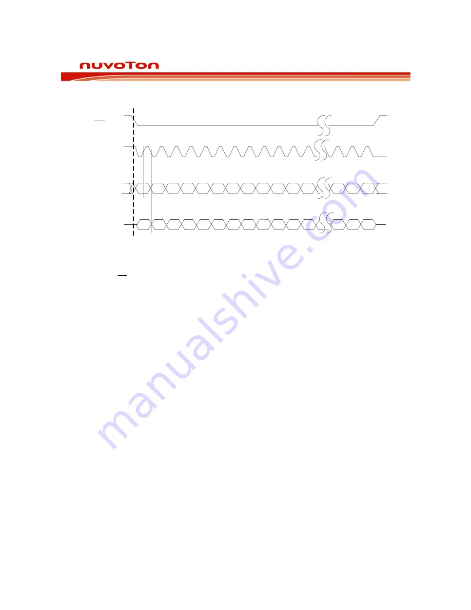
SPI Format
SS
LK
SO
SC
MI
LSB
Bz
By
Bx
X
B11
B10
B9
B8
B7
B6
B5
B4
B3
B2
B1
B0
MSB
MOSI
LSB
C0
C1
C2
C3 C4
C5
C6
C7
D0
D1
D2
D3 Dv
Dx
Dy
Dz
MSB
where Cn & Dn represent input data bit of MOSI, while Bn are output data bit.
The initial condition of the SPI inputs to the ISD1700 should be:
o
SS
= High
o
SCLK = High
o
MOSI = Low
10.3 SPI
C
OMMAND
O
VERVIEW
The SPI commands offer greater control over the device than that in standalone mode. There are
several types of commands:-
•
Priority
commands:
o
Accepted at any time and do not require state machine intervention.
o
PU, STOP, PD, RD_STATUS, CLR_INT, DEVID, RESET
•
Circular memory commands:
o
Execute operations similar to in Standalone mode.
o
PLAY, REC, FWD, ERASE, G_ERASE, RD_REC_PTR, RD_PLAY_PTR
•
Analog configuration commands:
o
Enable/disable various configuration paths, load/write APC and NVCFG registers, etc.
o
RD_APC, WR_APC, WR_NVCFG, LD_NVCFG, CHK_MEM,
•
Direct memory access commands:
o
Execute operations with start and end addresses.
o
SET_ERASE, SET_REC, SET_PLAY
A SPI command always consists of a command byte. The command byte has one special purpose
bit, bit 4 (LED). This bit controls the operation of the LED output. If the user wishes to enable the
operation of the LED, all opcodes should have this bit set to 1.


