ISD94100 Series Technical Reference Manual
Sep 9, 2019
Page
217
of 928
Rev1.09
IS
D
9
410
0
S
ER
IE
S
T
E
C
HN
ICA
L
RE
F
E
RE
NCE
M
AN
U
AL
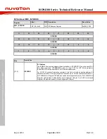
6.4.6
Register Description
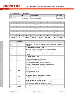
CONFIG0 (Address =
0x0030_0000)
31
30
29
28
27
26
25
24
CWDTEN[2]
Reserved
CFGXT1
CFOSC
Reserved
23
22
21
20
19
18
17
16
CBOV
CBORST
CBODEN
Reserved
15
14
13
12
11
10
9
8
Reserved
GPA8_LOW
CIOINI
Reserved
7
6
5
4
3
2
1
0
CBS
Reserved
CWDTE[1:0]
LOCK2
LOCK
DFEN
Bits
Descriptions
[31]
CWDTEN[2]
Watchdog Timer Hardware Enable Bit
When watchdog timer hardware enable function is enabled, the watchdog enable bit
WDTEN (WDT_CTL[7]) and watchdog reset enable bit RSTEN (WDT_CTL[1]) is set to 1
automatically after power on. The clock source of watchdog timer is forced to LIRC and LIRC
can’t be disabled.
CWDTEN[2:0]
is CONFIG0[31][4][3],
111 = WDT hardware enable function is inactive.
Others = WDT hardware enable function is active. WDT clock is always on.
[30:28]
Reserved
Reserved bit should always be programmed with 1.
[27]
CFGXT1
XTAL Multi-Function Select
0 = XTAL pins are configured as GPIO pins.
1 = XTAL pins are configured as external 4~24.576 MHz external high speed crystal
oscillator (HXT) pins.
[26]
CFOSC
CPU Clock Source Selection After Reset
The value of CFOSC will be loaded to HCLK (CLK_CLKSEL0[2:0]) in system clock controller
after any reset occurs. HCLK[2:0] = 111 if CFOSC = 1, HCLK[2:0] = 000 if CFGSC=0.
0 = External high speed crystal oscillator (HXT)
1 = Internal high speed RC oscillator (HIRC)
[25:24]
Reserved
Reserved bit should always be programmed with 1.
[23:21]
CBOV
Brown-Out Voltage Selection
000 = Brown-out voltage is 1.6V.
001 = Brown-out voltage is 1.8V.
010 = Brown-out voltage is 2.0V.
011 = Brown-out voltage is 2.2V.
100 = Brown-out voltage is 2.4V.
101 = Brown-out voltage is 2.6V.
110 = Brown-out voltage is 2.8V.
111 = Brown-out voltage is 3.0V.

