ISD94100 Series Technical Reference Manual
Sep 9, 2019
Page
241
of 928
Rev1.09
IS
D
9
410
0
S
ER
IE
S
T
E
C
HN
ICA
L
RE
F
E
RE
NCE
M
AN
U
AL
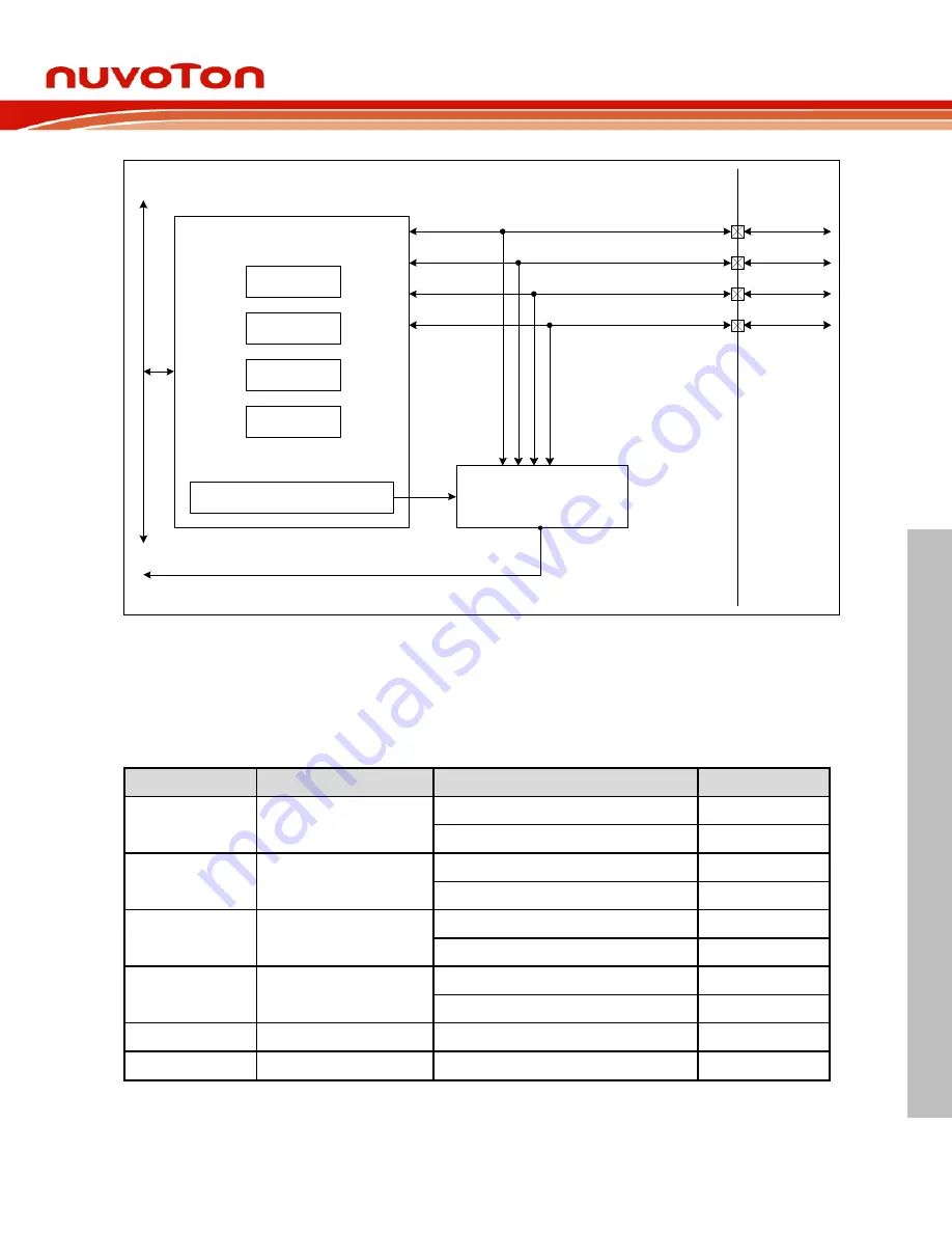
AHB Bus
PA[15:0]
PA[15:0]
Control Register
PB[15:13/9:0]
Control Register
PC[15:0]
Control Register
PD[15:0]
Control Register
De-bounce Control Register
Control Registers
Interrupt,
Wake-up Event
Detector
PB[15:13/9:0]
PC[15:0]
PD[15:0]
GPIO_INT
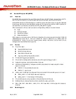
Figure 6.5-1 GPIO Controller Block Diagram
6.5.4
Basic Configuration
Reset configuration
–
Writing 1 to GPIORST bit (SYS_IPRST1[1]) resets GPIO controller
Pin configuration
Group
Pin Name
GPIO
MFP
INT0
INT0
PA.13
MFP2
PA.15
MFP1
INT1
INT1
PC.5
MFP1
PD.7
MFP2
INT2
INT2
PC.6
MFP1
PD.11
MFP2
INT3
INT3
PD.0
MFP1
PD.12
MFP2
INT4
INT4
PD.1
MFP1
INT5
INT5
PD.10
MFP1


