ISD94100 Series Technical Reference Manual
Sep 9, 2019
Page
267
of 928
Rev1.09
IS
D
9
410
0
S
ER
IE
S
T
E
C
HN
ICA
L
RE
F
E
RE
NCE
M
AN
U
AL
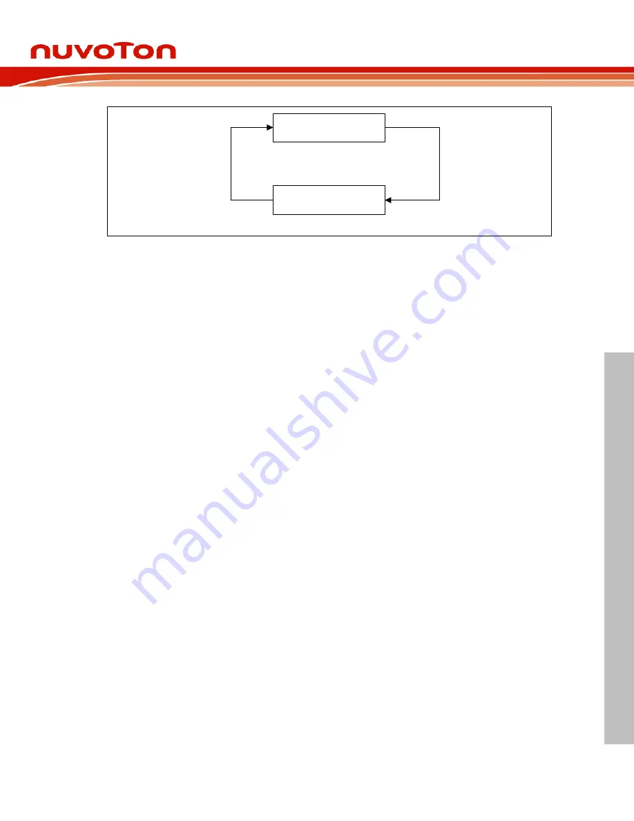
Idle State
Transfer State
OPMODE (PDMA_DSCTn_CTL[1:0]) = 0x1
OPMODE (PDMA_DSCTn_CTL[1:0]) = 0x0
Transfer done
Next Request
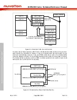
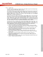
Figure 6.6-3 Basic Mode Finite State Machine
Scatter-Gather Mode
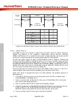
Scatter-Gather mode is a complex mode and can perform sophisticated transfer through the use of
the description link list table as shown in Figure 6.6-4. Through operation mode user can perform
peripheral wrapper-around, multiple PDMA task or can be used for data transfer between varied
locations in system memory instead of a set of contiguous locations. Scatter-gather mode only need
a request to finish all table entries task until the last task with OPMODE (PDMA_DSCTn_CTL[1:0])
is idle state without ack, it also means scatter-gather mode can only be use to transfer data between
memory to memory without handshaking.
In Scatter-Gather mode, the table is just used for jumping to the next table entry. The first task will
not perform any operation transfer. Finishing each task will generate an interrupt to CPU if
corresponding PDMA interrupt bit is enabled and TBINTDIS (PDMA_DSCTn_CTL[7]) bit is “0”
(when finishing task and TBINTDIS bit is “0”, corresponding TDIFn (PDMA_TDSTS[15:0]) flag will
be asserted and if this bit is “1” TDIFn will not be active).
If channel 7 has been triggered, and the operation mode is in Scatter-Gather mode (OPMODE
(PDMA_DSCTn_CTL[1:0]) = 0x2), the hardware will load the real PDMA information task from the
address generated by adding PDMA_DSCTn_NEXT (link address) and PDMA_SCATBA (base
address) registers. For example, base address is 0x2000_0000 (only MSB 16bits valid in
PDMA_SCATBA), current link address is 0x0000_0100 (only LSB 16bits without last two bits [1:0]
valid in PDMA_DSCTn_NEXT), then next DSCT entry start address is 0x2000_0100. Note that the
address of descriptor tables must be in the same 64KB area.


