ISD94100 Series Technical Reference Manual
Sep 9, 2019
Page
319
of 928
Rev1.09
IS
D
9
410
0
S
ER
IE
S
T
E
C
HN
ICA
L
RE
F
E
RE
NCE
M
AN
U
AL
Bits
Description
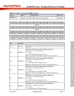
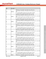
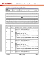
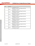
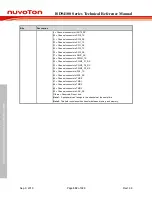
1 = PDMA channel 11 source address or destination address is not follow transfer width
setting.
Note:
Software can write 1 to clear this bit.
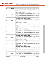
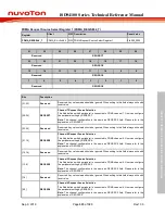
[10]
ALIGN10
PDMA Channel 10 Transfer Alignment Flag Register
0 = PDMA channel 10 source address and destination address both follow transfer width
setting.
1 = PDMA channel 10 source address or destination address is not follow transfer width
setting.
Note:
Software can write 1 to clear this bit.
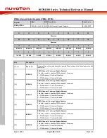
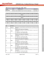
[9]
ALIGN9
PDMA Channel 9 Transfer Alignment Flag Register
0 = PDMA channel 9 source address and destination address both follow transfer width
setting.
1 = PDMA channel 9 source address or destination address is not follow transfer width
setting.
Note:
Software can write 1 to clear this bit.
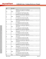
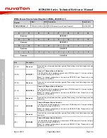
[8]
ALIGN8
PDMA Channel 8 Transfer Alignment Flag Register
0 = PDMA channel 8 source address and destination address both follow transfer width
setting.
1 = PDMA channel 8 source address or destination address is not follow transfer width
setting.
Note:
Software can write 1 to clear this bit.
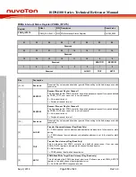
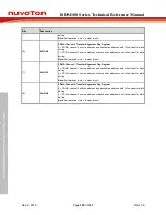
[7]
ALIGN7
PDMA Channel 7 Transfer Alignment Flag Register
0 = PDMA channel 7 source address and destination address both follow transfer width
setting.
1 = PDMA channel 7 source address or destination address is not follow transfer width
setting.
Note:
Software can write 1 to clear this bit.
[6]
ALIGN6
PDMA Channel 6 Transfer Alignment Flag Register
0 = PDMA channel 6 source address and destination address both follow transfer width
setting.
1 = PDMA channel 6 source address or destination address is not follow transfer width
setting.
Note:
Software can write 1 to clear this bit.
[5]
ALIGN5
PDMA Channel 5 Transfer Alignment Flag Register
0 = PDMA channel 5 source address and destination address both follow transfer width
setting.
1 = PDMA channel 5 source address or destination address is not follow transfer width
setting.
Note:
Software can write 1 to clear this bit.
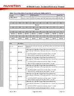
[4]
ALIGN4
PDMA Channel 4 Transfer Alignment Flag Register
0 = PDMA channel 4 source address and destination address both follow transfer width
setting.
1 = PDMA channel 4 source address or destination address is not follow transfer width
setting.
Note:
Software can write 1 to clear this bit.
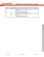
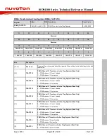
[3]
ALIGN3
PDMA Channel 3 Transfer Alignment Flag Register
0 = PDMA channel 3 source address and destination address both follow transfer width
setting.
1 = PDMA channel 3 source address or destination address is not follow transfer width

