ISD94100 Series Technical Reference Manual
Sep 9, 2019
Page
349
of 928
Rev1.09
IS
D
9
410
0
S
ER
IE
S
T
E
C
HN
ICA
L
RE
F
E
RE
NCE
M
AN
U
AL
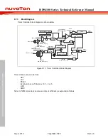
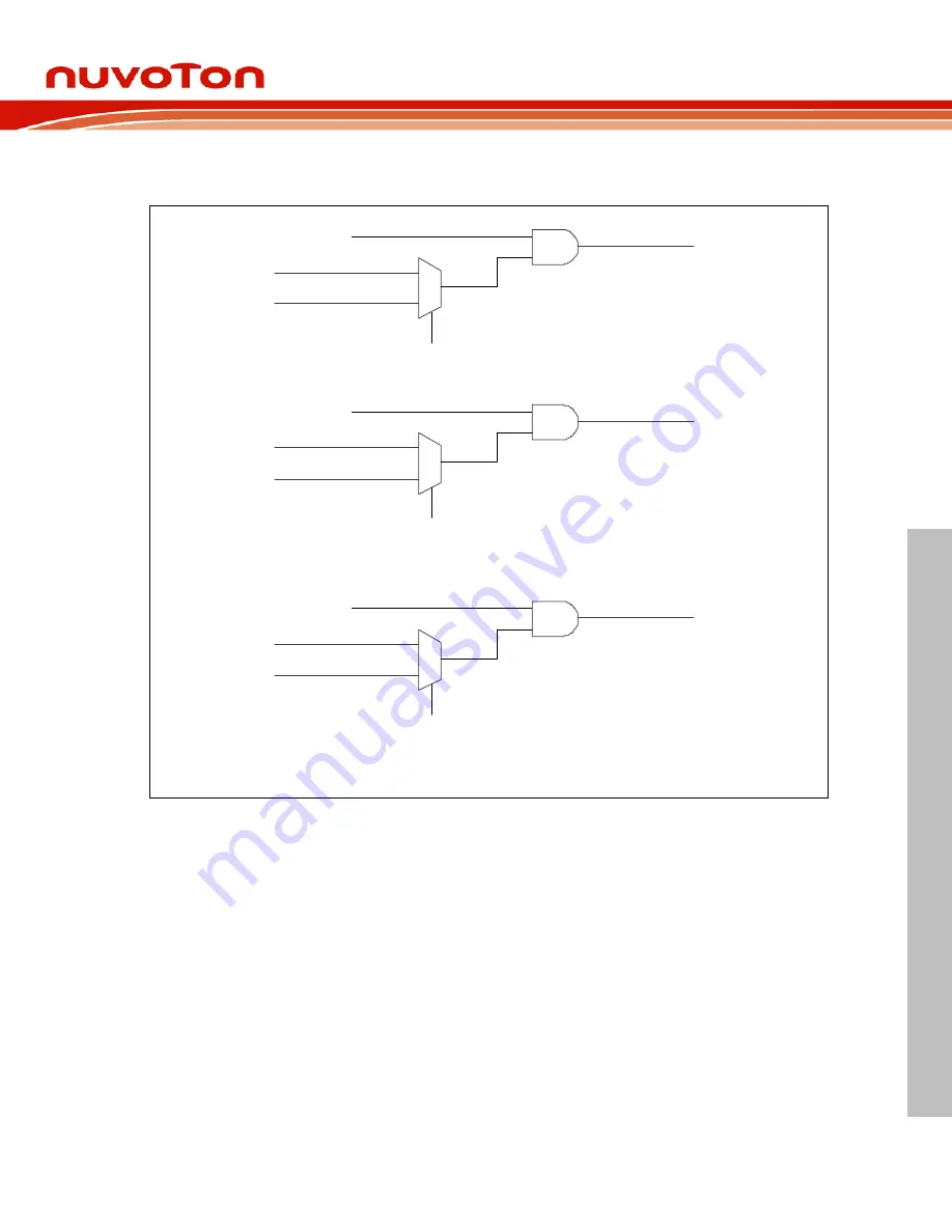
When the TRGPDMA (TIMERx_TRGCTL[4]) is set, if the timer interrupt signal is generated, the
timer controller will trigger PDMA.
0
1
TRGSSEL
(TIMERx_TRGCTL[0])
Trigger PWM
TRGPWM(TIMERx_TRGCTL[1])
time-out interrupt signal
capture interrupt signal
0
1
TRGSSEL
(TIMERx_TRGCTL[0])
Trigger ADC
TRGADC(TIMERx_TRGCTL[2])
time-out interrupt signal
capture interrupt signal
0
1
TRGSSEL
(TIMERx_TRGCTL[0])
Trigger PDMA
TRGPDMA(TIMERx_TRGCTL[4])
time-out interrupt signal
capture interrupt signal
Figure 6.7-11 Internal Timer Trigger
6.7.5.11 Inter-Timer Trigger Capture Mode
In this mode, the Timer0/2 will be forced in event counting mode, counting with external event, and
will generate an internal signal (INTR_TMR_TRG) to trigger Timer1/3 start or stop counting. Also,
the Timer1/3 will be forced in capture mode and start/stop trigger-counting by Timer0/2 counter
status.
Setting Timer0 Inter-timer Trigger Capture enabled, trigger-counting capture function is forced on
Timer1. Setting Timer2 Inter-Timer Trigger enabled, trigger-counting capture function is forced on
Timer3.
•
Start Trigger
While INTRGEN (TIMERx_CTL[19]) in Timer0/2 is set, the Timer0/2 will make a rising-edge
transition of INTR_TMR_TRG while Timer0/2 24-bit counter value (CNT) is counting from 0x0 to
0x1 and Timer1/3 counter will start counting immediately and automatically.
Stop Trigger
When Timer0/2 CNT reaches the Timer0/2 CMPDAT value, the Timer0/2 will make a falling-edge


