ISD94100 Series Technical Reference Manual
Sep 9, 2019
Page
368
of 928
Rev1.09
IS
D
9
410
0
S
ER
IE
S
T
E
C
HN
ICA
L
RE
F
E
RE
NCE
M
AN
U
AL
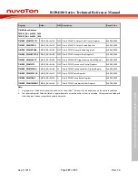
6.7.8
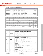
Register Description
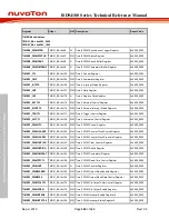
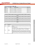
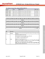
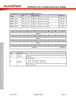
Timer Control Register (TIMERx_CTL)
Register
Offset
R/W Description
Reset Value
TIMER0_CTL
T0x00
R/W Timer0 Control Register
0x0000_0005
TIMER1_CTL
T0x100
R/W Timer1 Control Register
0x0000_0005
TIMER2_CTL
T0x00
R/W Timer2 Control Register
0x0000_0005
TIMER3_CTL
T0x100
R/W Timer3 Control Register
0x0000_0005
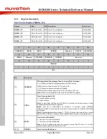
31
30
29
28
27
26
25
24
ICEDEBUG
CNTEN
INTEN
OPMODE
Reserved
ACTSTS
EXTCNTEN
23
22
21
20
19
18
17
16
WKEN
Reserved
TGLPINSEL
PERIOSEL
INTRGEN
Reserved
15
14
13
12
11
10
9
8
Reserved
7
6
5
4
3
2
1
0
PSC
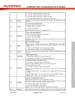
Bits
Description
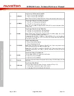
[31]
ICEDEBUG
ICE Debug Mode Acknowledge Disable Control (Write Protected)
0 = ICE debug mode acknowledgement effects TIMER counting.
TIMER counter will be held while CPU is held by ICE.
1 = ICE debug mode acknowledgement Disabled.
TIMER counter will keep going no matter CPU is held by ICE or not.
Note:
This bit is write protected. Refer to the SYS_REGLCTL register.
[30]
CNTEN
Timer Counting Enable Bit
0 = Stops/Suspends counting.
1 = Starts counting.
Note1:
In stop status, and then set CNTEN to 1 will enable the 24-bit up counter to keep
counting from the last stop counting value.
Note2:
This bit is auto-cleared by hardware in one-shot mode OPMODE
(TIMER_CTL[28:27] = 00) when the timer time-out interrupt flag TIF (TIMERx_INTSTS[0])
is generated.
Note3:
Set enable/disable this bit needs 2 * TMR_CLK period to become active, user can
read ACTSTS (TIMERx_CTL[25]) to check enable/disable command is completed or not.
[29]
INTEN
Timer Interrupt Enable Bit
0 = Timer time-out interrupt Disabled.
1 = Timer time-out interrupt Enabled.
Note:
If this bit is enabled, when the timer time-out interrupt flag TIF is set to 1, the timer
interrupt signal is generated and inform to CPU.
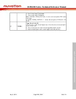
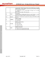
[28:27]
OPMODE
Timer Counting Mode Select


