ISD94100 Series Technical Reference Manual
Sep 9, 2019
Page
518
of 928
Rev1.09
IS
D
9
410
0
S
ER
IE
S
T
E
C
HN
ICA
L
RE
F
E
RE
NCE
M
AN
U
AL
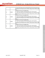
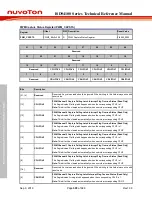
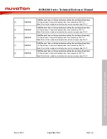
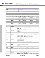
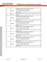
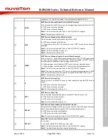
This bit is writing 1 to clear.
0 = No capture falling latch condition happened.
1 = Capture falling latch condition happened, this flag will be set to high.
Note:
When Capture with PDMA operating, CAPIF corresponding channel CFLIF will
cleared by hardware after PDMA transfer data.
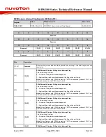
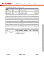
[8]
CFLIF0
PWM Channel 0 Capture Falling Latch Interrupt Flag
This bit is writing 1 to clear.
0 = No capture falling latch condition happened.
1 = Capture falling latch condition happened, this flag will be set to high.
Note:
When Capture with PDMA operating, CAPIF corresponding channel CFLIF will
cleared by hardware after PDMA transfer data.
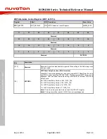
[7:6]
Reserved
Reserved. Any values read should be ignored. When writing to this field always write with
reset value.
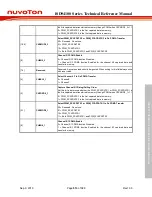
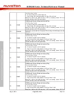
[5]
CRLIF5
PWM Channel 5 Capture Rising Latch Interrupt Flag
This bit is writing 1 to clear.
0 = No capture rising latch condition happened.
1 = Capture rising latch condition happened, this flag will be set to high.
Note:
When Capture with PDMA operating, CAPIF corresponding channel CRLIF will
cleared by hardware after PDMA transfer data.
[4]
CRLIF4
PWM Channel 4 Capture Rising Latch Interrupt Flag
This bit is writing 1 to clear.
0 = No capture rising latch condition happened.
1 = Capture rising latch condition happened, this flag will be set to high.
Note:
When Capture with PDMA operating, CAPIF corresponding channel CRLIF will
cleared by hardware after PDMA transfer data.
[3]
CRLIF3
PWM Channel 3 Capture Rising Latch Interrupt Flag
This bit is writing 1 to clear.
0 = No capture rising latch condition happened.
1 = Capture rising latch condition happened, this flag will be set to high.
Note:
When Capture with PDMA operating, CAPIF corresponding channel CRLIF will
cleared by hardware after PDMA transfer data.
[2]
CRLIF2
PWM Channel 2 Capture Rising Latch Interrupt Flag
This bit is writing 1 to clear.
0 = No capture rising latch condition happened.
1 = Capture rising latch condition happened, this flag will be set to high.
Note:
When Capture with PDMA operating, CAPIF corresponding channel CRLIF will
cleared by hardware after PDMA transfer data.
[1]
CRLIF1
PWM Channel 1 Capture Rising Latch Interrupt Flag
This bit is writing 1 to clear.
0 = No capture rising latch condition happened.
1 = Capture rising latch condition happened, this flag will be set to high.
Note:
When Capture with PDMA operating, CAPIF corresponding channel CRLIF will
cleared by hardware after PDMA transfer data.
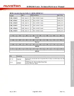
[0]
CRLIF0
PWM Channel 0 Capture Rising Latch Interrupt Flag
This bit is writing 1 to clear.
0 = No capture rising latch condition happened.
1 = Capture rising latch condition happened, this flag will be set to high.
Note:
When Capture with PDMA operating, CAPIF corresponding channel CRLIF will


