ISD94100 Series Technical Reference Manual
Sep 9, 2019
Page
527
of 928
Rev1.09
IS
D
9
410
0
S
ER
IE
S
T
E
C
HN
ICA
L
RE
F
E
RE
NCE
M
AN
U
AL
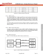
011
2
10
* T
WDT
(3/18/130/1026) * T
WDT
100
2
12
* T
WDT
(3/18/130/1026) * T
WDT
101
2
14
* T
WDT
(3/18/130/1026) * T
WDT
110
2
16
* T
WDT
(3/18/130/1026) * T
WDT
111
2
18
* T
WDT
(3/18/130/1026) * T
WDT
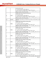
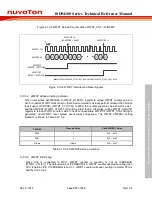
Table 6.9.5-1 Watchdog Timer Time-out Interval Period Selection
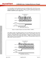
T
TIS
WDT reset
(low reset)
T
RSTD
T
RST
T
WDT
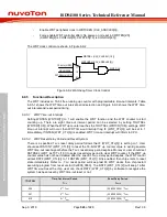
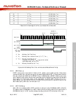
•
T
WDT
: Watchdog Clock Time Period
•
T
TIS
: Watchdog Time-out Interval Period ( (2
4
~ 2
18
) * T
WDT
)
•
T
RSTD
: Watchdog Reset Delay Period
- Selectable 3/18/130/1026 * T
WDT
delay period controlled
by RSTDSEL(WDT_ALTCTL [1:0])
•
T
RST
: Watchdog Reset Period ( 63 * T
WDT
)
WDT_CLK
IF = 1
RSTF = 1
(if RSTEN = 1)
IF
(WDT_CTL[3])
RSTF
(WDT_CTL[2])
RSTEN
(WDT_CTL[1])
Figure 6.9-3 Watchdog Timer Time-out Interval and Reset Period Timing
6.9.5.3
WDT Wake-up
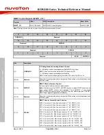
If WDT clock source is selected to 10 kHz or LXT, system can be waken-up from Power-down
mode while WDT time-out interrupt signal is generated and WKEN (WDT_CTL[4]) enabled. Notice
that user should set LXTEN (CLK_PWRCTL [1]) or LIRCEN (CLK_PWRCTL [3]) to select clock
source before system entries Power-down mode because the system peripheral clock are disabled
when system is Power-down mode. In the meanwhile, the WKF (WDT_CTL[5]) will set to 1
automatically, user can check WKF (WDT_CTL[5]) status by software to recognize the system has
been waken-up by WDT time-out interrupt or not.
6.9.5.4
WDT ICE Debug
When ICE is connected to MCU, WDT counter is counting or not by ICEDEBUG (WDT_CTL[31]).
The default value of ICEDEBUG is 0, WDT counter will stop counting when CPU is held by ICE. If
ICEDEBUG is set to 1, WDT counter will keep counting no matter CPU is held by ICE or not.

