ISD94100 Series Technical Reference Manual
Sep 9, 2019
Page
54
of 928
Rev1.09
IS
D
9
410
0
S
ER
IE
S
T
E
C
HN
ICA
L
RE
F
E
RE
NCE
M
AN
U
AL
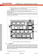
Digital power from V
DD
and V
SS
: supplies the power to the internal regulator which
provides a regulated 1.2 V power for digital operation.
USB transceiver power from USB_V
DD33
offers the power for operating the USB
transceiver.
Analog power (AV
DD
) should be at the same voltage level as digital power (V
DD
).
Both power supplies should have decoupling capacitors placed as close as possible to pins
preferably with no via.
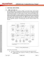
The outputs of internal voltage regulator, LDO_CAP, requires an external capacitor which should
be located close to LDO_CAP pin and returned directly to V
SS
. The Figure 6.2-4 shows the power
distribution of the ISD94100 series.
AV
DD
AV
SS
V
DD
SRAM
V
DD
to 1.2V
LDO
POR33
PLL
Flash
Power On
Control
PB.5
PB.6
GPIOs except
PB.13~PB.15
1.2V
LDO_CAP
1uF
I94100 Series Power Distribution
PC.0
PC.1
V
SS
POR12
IO Cell
10 KHz
LIRC
Oscillator
48.0/49.152
MHz HIRC
Oscillator
32.768 kHz
crystal
oscillator
Digital
Logic
4~24.576
MHz crystal
oscillator
Low Voltage Reset
Brown-out Detector
12-bit ADC
PB.13~PB.15
USB
_
V
DD
33
USB
_
V
SS
IO Cell
USB 1.1
PHY
Figure 6.2-4 ISD94100 Series Power Distribution Diagram
6.2.4
Power Modes
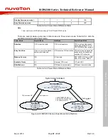
The ISD94100 series power mode include Normal mode, Idle mode and Power-down mode. The
system starts up in Normal mode. In Idle mode, only CPU clock is disabled while other peripherals
work normally. If system is waiting for an interrupt only, the user can set system in Idle mode to
save power and wake-up quickly. The user can set system into Power-down mode when system
does not need to work for a long time. ISD94100 series provides several power-down modes with
different power consumption level.
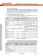
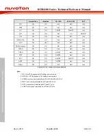
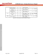
The ISD94100 series includes the following power modes:


