ISD94100 Series Technical Reference Manual
Sep 9, 2019
Page
622
of 928
Rev1.09
IS
D
9
410
0
S
ER
IE
S
T
E
C
HN
ICA
L
RE
F
E
RE
NCE
M
AN
U
AL
6.13.5.1.3 Slave Address Transmission
After a START (or Repeated START) condition, the master sends slave address to the SDA line.
•
In 7-bit address mode, one address byte is to be sent.
–
To enter Transmitter mode, a master sends the slave address with LSB reset (i.e. as 0).
–
To enter Receiver mode, a master sends the slave address with LSB set (i.e. as 1).
•
In 10-bit address mode,
–
To enter Transmitter mode, a master sends the 1
st
header byte (11110xx0) followed by
the 2
nd
address byte which contains the slave’s lower 8 bit address, (where xx denotes
the two most significant bits of the address).
–
To enter Receiver mode, a master sends the 1
st
header byte (11110xx0) followed by the
2
nd
address byte. Then the master should send a Repeated START condition followed by
header (11110xx1), (where xx denotes the two most significant bits of the address).
In either mode, the slave with matching address should send acknowledge bit after the addressing
byte(s), so the communication can continue.
6.13.5.1.4 Data Transfer
When a slave receives a correct address with an R/W bit, the data will follow R/W bit specified to
transfer. Each transferred byte is followed by an acknowledge bit on the 9th SCL clock cycle. If the
slave signals a Not Acknowledge (NACK), the master can generate a STOP signal to abort the data
transfer or generate a Repeated START signal and start a new transfer cycle.
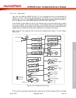
If the master, as a receiving device, does Not Acknowledge (NACK) the slave, the slave releases
the SDA line for the master to generate a STOP or Repeated START signal. The Figure 6.13-6 and
Figure 6.13-7 shows the waveform of bit transfer and acknowledge.
SDA
SCL
Data line stable;
data valid
Change of data
allowed
Figure 6.13-6 Bit Transfer on the I
2
C Bus

