ISD94100 Series Technical Reference Manual
Sep 9, 2019
Page
625
of 928
Rev1.09
IS
D
9
410
0
S
ER
IE
S
T
E
C
HN
ICA
L
RE
F
E
RE
NCE
M
AN
U
AL
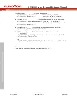
The code snippet below shows the I2C module initialization procedure:
FMC->ISPCMD = FMC_ISPCMD_READ;
// op code for 32-bit read is 0x00
CLK_EnableModuleClock(I2C0_MODULE);
I2C_Open(I2C0, 100000);
// set clock to 100K, and enable I2C_CTL_I2CEN_Msk in I2C_CTL
I2C_SetSlaveAddr(I2C0, 0, 0x15, I2C_GCMODE_DISABLE); /* Slave Address : 0x15 */
…
I2C_EnableInt(I2C0);
NVIC_EnableIRQ(I2C0_IRQn);
Writing 1 to INTEN bit in I2C_CTL register enables the I2C interrupt. I2C interrupt is generated at
the 9
th
clock, i.e. after master/slave received ACK/NACK. The interrupt service routine (ISR) should
check the I2C_STATUS value, and handle the I2C transaction via I2C_CTL control bits and
I2C_DAT data register.
Four control bits in I2C_CTL register are frequently used:
STA: writing 1 to STA bit generates a START (or repeated START) condition. This bit will
be automatically cleared by hardware.
STO: writing 1 to STO bit generates a STOP condition. This bit will be automatically
cleared by hardware.
SI: Interrupt flag is set by hardware, software must write 1 to SI bit to clear the I2C interrupt
flag.
AA: 1- return acknowledge after a byte is received (matched address or data). 0 – return
Not Acknowledge (NACK).
For more details of I2C registers, refer to section “I2C Protocol Registers” and “Register
Description”.
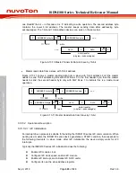
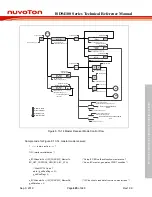
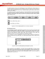
Figure 6.13-12 shows an example of master side flow control: software reads I2C_Status, if it reads
value 0x08 (START condition sent), then set I2C_DATA=SLA+W and (STA,STO,SI,AA) = (0,0,1,x)
to send the address to I
2
C bus. An ACK is expected from the slave with the matching address. After
ACK is received, the I2C_STATUS will be updated by status code 0x18.
S
I2C_DAT
(SLA+W)
ACK
Last Status
STATUS=0x08
Updated Status
STATUS=0x18
Register Control
I2C_DAT=SLA+W
(STA,STO,SI,AA)=(0,0,1,x)
Master to Slave
Slave to Master
Figure 6.13-12 Control I
2
C Bus according to the current I
2
C Status
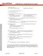
Sample code for Figure 6.13-12
if (u32Status == 0x08) {
/* START has been transmitted and prepare SLA+W */
I2C_SET_DATA(I2C0, (g_u8DeviceAddr << 1)); /* Write SLA+W to Register I2CDAT */
I2C_SET_CONTROL_REG(I2C0, I2C_SI);
/* STA =0, STO=0; SI = 1 to clear the interrupt flag */
} else if (u32Status == 0x18) {
/* SLA+W has been transmitted and ACK has been received */
…
}


