ISD94100 Series Technical Reference Manual
Sep 9, 2019
Page
687
of 928
Rev1.09
IS
D
9
410
0
S
ER
IE
S
T
E
C
HN
ICA
L
RE
F
E
RE
NCE
M
AN
U
AL
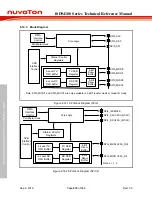
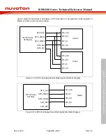
SPIx_CLK
SPIx_MISOz
SPIx_MOSIz
SPIx_SSy
SPI_CLK
SPI_DATA
SPI_SS
I94120 Series
SPI Master
Slave
Note:
x: Controller number (x = 0, 1, 2), y: Slave selection pin channel number in SPI0 (y =
z: MOSI and MISO pin channel number in SPI0 (z = 0)
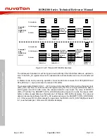
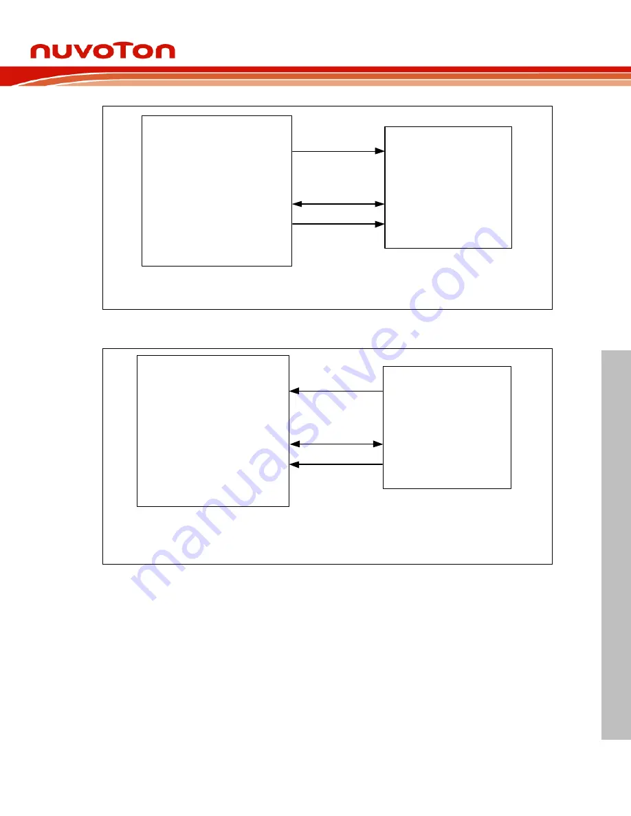
Figure 6.14-14 SPI Half-Duplex Master Mode Application Block Diagram
SPIx_CLK
SPIx_MISOz
SPIx_MOSIz
SPIx_SSy
SPI_CLK
SPI_DATA
SPI_SS
I94120 Series
SPI Slave
Master
Note:
x: Controller number (x = 0, 1, 2), y: Slave selection pin channel number in SPI0 (y = 0, 1),
z: MOSI and MISO pin channel number in SPI0 (z = 0)
Figure 6.14-15 SPI Half-Duplex Slave Mode Application Block Diagram
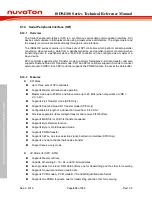
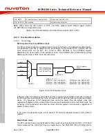
6.14.5.5 Receive-Only Mode
In SPI Master device, it can communicate in receive-only mode by setting RXONLY
(SPIn_CTL[15]). In this configuration, the SPI Master device will generate SPI bus clock
continuously as long as the receive-only mode is enabled for receiving data bit from SPI slave
device. If AUTOSS (SPIn_SSCTL[3]) is enabled in receive-only mode, SPI Master will keep
activating the slave select signal.
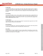
The remaining SPI0_MOSI0 and SPIx_MOSI (x=1, 2) pin of SPI Master device is not used for
communication and can be configured as GPIO. The status BUSY (SPIn_STATUS[0]) will be
asserted in receive-only mode due to the generation of SPI bus clock. Entering this mode will
produce the TXRST (SPIn_FIFOCTL[1]) and RXRST (SPIn_FIFOCTL[0]) at the same time
automatically. After enabling this mode, the output SPI bus clock will be sent out in 6 peripheral
clock cycles. In this mode, the data which has been written into transmit FIFO will be loaded into
transmit shift register and sent out.

