ISD94100 Series Technical Reference Manual
Sep 9, 2019
Page
757
of 928
Rev1.09
IS
D
9
410
0
S
ER
IE
S
T
E
C
HN
ICA
L
RE
F
E
RE
NCE
M
AN
U
AL
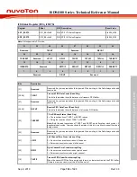
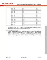
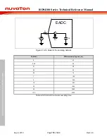
EADC0_CH2
PA.2
MFP2
EADC0_CH3
PA.3
MFP2
EADC0_CH4
PA.4
MFP2
EADC0_CH5
PA.5
MFP2
EADC0_CH6
PA.6
MFP2
EADC0_CH7
PA.7
MFP2
EADC0_CH8
PA.8
MFP2
EADC0_CH9
PA.9
MFP2
EADC0_CH10
PD.13
MFP2
EADC0_CH11
PD.14
MFP2
EADC0_CH12
PD.15
MFP2
EADC0_ST
PA.10
MFP2
PD.10
MFP2
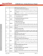
Note:
After the EADC pins is configured to ADC analog input, corresponding DINOFF
(Px_DINOFF[31:16]) should be set to 1 to disable digital input path.
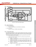
6.16.5 Functional Description
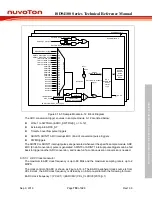
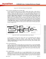
The EADC controller consists of a 13 channel analog switch, 13 sample modules and a 12-bit
successive approximation analog-to-digital converter. The EADC operation is based on sample
module 0~12, each of them has its configuration to decide which trigger source to start the
conversion, which channel to convert. Sample module 0~12 can be configured to EADC_CH0~12
channel, and different trigger source. It provides user a flexible means to get the over-sampling
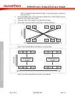
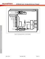
results. The sample module 0~3 and sample module 4~12 are shows as follows.

