ISD94100 Series Technical Reference Manual
Sep 9, 2019
Page
759
of 928
Rev1.09
IS
D
9
410
0
S
ER
IE
S
T
E
C
HN
ICA
L
RE
F
E
RE
NCE
M
AN
U
AL
Disable hardware Trigger
19
to
1
MUX
TRGSEL(EADC_SCTL4[20:16])
EADC0_ST pin signal
ADC
Sample and
Priority
control
Logic
Sample
Module 4
Result
Register
DAT4
CHSEL
(EADC_SCTL4[3:0]
ADINT0 interrupt EOC pulse
ADINT1 interrupt EOC pulse
Sample Module
4
Sample Module
12
TRGDLYDIV (EADC_SCTL4[7:6])
SWTRG4~12 Software
trigger
0h
1h
Fh
8-bit Up
Counter
TRGDLYCNT
(EADC_SCTL4[15:8])
/1, /2, /4, /16
ADC_CLK
=
reset
EOC4
reset pulse
Eh
9h
5h
2h
3h
Ah
Bh
Ch
Dh
EOC4
Timer0 overflow pulse
4h
Timer1 overflow pulse
Timer2 overflow pulse
Timer3 overflow pulse
6h
7h
8h
10h
11h
12h
13h
PWM0TG0
PWM0TG1
PWM0TG2
PWM0TG3
PWM0TG4
PWM0TG5
Reserved
Reserved
Reserved
Reserved
Reserved
Reserved
EXTREN (EADC_SCTL4[4])
EXTFEN (EADC_SCTL4[5])
14h
15h
Reserved
Reserved
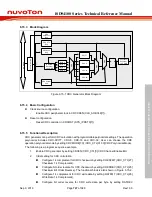
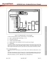
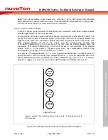
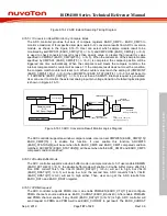
Figure 6.16-3 Sample Module 4~12 Block Diagram
The ADC conversion trigger sources in sample module 0~12 are listed below:
Write 1 to SWTRGn (EADC_SWTRG[n], n = 0~12)
External pin EADC0_ST
Timer0~3 overflow pulse triggers
ADINT0, ADINT1 ADC interrupt EOC (End of conversion) pulse triggers
PWM triggers
The ADINT0 or ADINT1 interrupt pulses are generated whenever the specific sample module ADC
EOC (End of conversion) pulse is generated. ADINT0 or ADINT1 interrupt pulse triggers can be fed
back to trigger another ADC conversion, and is useful if a continuous scan conversion is needed.
6.16.5.1 ADC Clock Generator
The maximum EADC clock frequency is up to 60 MHz and the maximum sampling rate is up to 2
MSPS.
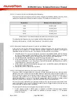
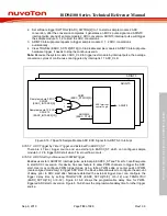
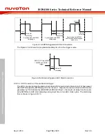
The clock control of EADC is shown as Figure 6.16-4. The EADC peripheral clock source is from
HCLK clock, the ADC clock frequency is divided by an 8-bit pre-scalar with the following formula :
EADC clock frequency = (PCLK1) / (EADCDIV (CKL_CLKDIV0[23:16])+1)


