ISD94100 Series Technical Reference Manual
Sep 9, 2019
Page
766
of 928
Rev1.09
IS
D
9
410
0
S
ER
IE
S
T
E
C
HN
ICA
L
RE
F
E
RE
NCE
M
AN
U
AL
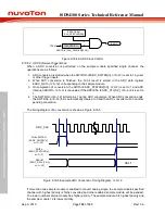
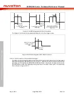
EADC0_ST
PCLK
EADC0_ST rising
detect
EADC0_ST falling
detect
2 PCLK
3 PCLK
2 PCLK
3 PCLK
Figure 6.16-11 EADC0_ST De-bounce Timing Diagram
6.16.5.10 ADC Extend Sampling Time
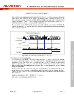
When ADC operation at high ADC clock rate, the sampling time of analog input voltage may not
enough if the analog channel has heavy loading to cause fully charge time is longer. User can set
extend sampling time by writing EXTSMPT (EADC_SCTLn[31:24], n=0~12) for each sample
module. The ADC extend sampling time is present between ADC controller judge which channel to
be converting and ADC start to conversion. The range of extend sampling time is from 0 ~255 ADC
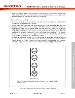
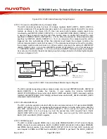
clock. The extended sampling time is shown in Figure 6.16-12.
Sampling
A/D converter
start
A/D clock
A/D converter
Sample/Hold
Hold
A/D Conversion
Sampling
A/D converter
finish
Extend Sampling Time
(N ADC clocks)
Hold
2
3
1
A/D converter
channel select
14 ADC clocks
Note:
N = EXTSMPT (EADC_SCTLn[31:24], n=0~12) (Extend sampling cycle for each sample module)
ADIFn (EADC_STATUS2[3:0], n=0~3)
INTPOS (EADC_SCTLn[22], n=0~12)
ADIFn (INTPOS=0)
ADIFn (INTPOS=1)


