ISD94100 Series Technical Reference Manual
Sep 9, 2019
Page
803
of 928
Rev1.09
IS
D
9
410
0
S
ER
IE
S
T
E
C
HN
ICA
L
RE
F
E
RE
NCE
M
AN
U
AL
6.17.5 Functional Description
6.17.5.1 I
2
S Clock
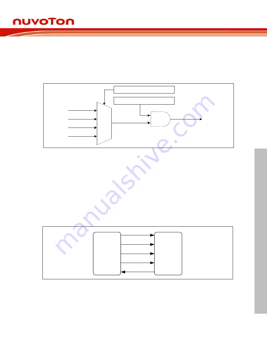
The I
2
S controller has four clock sources selected by I2SSEL (CLK_CLKSEL3[17:16]). The I
2
S
clock rate must be slower than or equal to system clock rate.
11
10
01
00
PCLK0
PLL
HXT
HIRC
I2SSEL (CLK_CLKSEL3 [17:16])
I2SCKEN (CLK_APBCLK0 [29])
I2S_CLK
HIRC: High Speed Internal RC oscillator
HXT : High Speed External Crystal Clock
Figure 6.17-2 I
2
S Clock Control Diagram
6.17.5.2 Master/Slave Interface
The I
2
S function can operate as master or slave mode by setting SLAVE (I2S_CTL0[8]) to
communicate with other I
2
S slave or master. The serial bus clock I2S_BCLK is permanently
generated by the master even through there is no transferring data bit at the moment. The word
select signal I2S_LRCLK is also generated by the master and it indicates the beginning of a new
data word and the targeted audio channel. Both the I2S_LRCLK and the transmitting data change
synchronously to the falling edges of I2S_BCLK.
In some applications, especially for Audio-ADC or Audio-DAC, a master clock signal, I2S_MCLK,
is required with a fixed phase relation to the I2S_BCLK. The I2S_MCLK is enabled by MCLKEN
(I2S_CTL0[15]). In Master mode, the I2S_MCLK, I2S_BCLK, I2S_LRCLK is output to device slave.
And if in slave mode, the I2S_MCLK is output to master, and I2S_BCLK or I2S_LRCLK is input
from master.
I
2
S
Master
I2S_MCLK
I2S_BCLK
I2S_LRCLK
I2S_DO
I2S_DI
Slave
Figure 6.17-3 Master mode Interface Block Diagram


