ISD94100 Series Technical Reference Manual
Sep 9, 2019
Page
806
of 928
Rev1.09
IS
D
9
410
0
S
ER
IE
S
T
E
C
HN
ICA
L
RE
F
E
RE
NCE
M
AN
U
AL
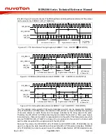
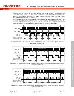
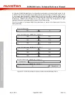
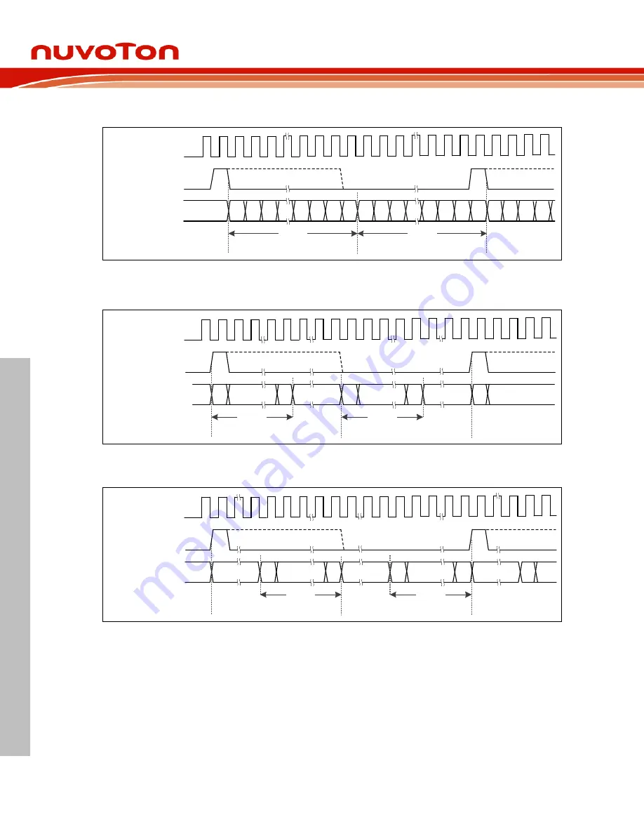
PCM with MSB justified, and PCM with LSB justified data format.
I2S_BCLK
I2S_LRCLK
I2S_DI /
I2S_DO
Data width
Data width
Left channel of frame N
Right channel of frame N
Left channel
of frame N+1
LSB MSB
MSB
LSB
MSB
Figure 6.17-10 Standard PCM Audio Timing Diagram (FORMAT = 0x4 ; CHWIDTH
≦
DATWIDTH)
MSB
I2S_BCLK
I2S_LRCLK
I2S_DI /
I2S_DO
Redundant
Zero Pad
Redundant
Zero Pad
Data width
Data width
LSB
MSB
MSB
LSB
Left channel of frame N
Right channel of frame N
Left channel
of frame N+1
…
…
Figure 6.17-11 PCM with MSB Justified Data Format (FORMAT = 0x5 ; CHWIDTH > DATWIDTH)
MSB
I2S_BCLK
I2S_LRCLK
I2S_DI /
I2S_DO
Redundant
Zero Pad
Redundant
Zero Pad
Data width
Data width
LSB
MSB
MSB
LSB
Left channel of frame N
Right channel of frame N
Left channel
of frame N+1
Redundant
Zero Pad
…
…
Figure 6.17-12 PCM with LSB Justified Data Format (FORMAT = 0x6 ; CHWIDTH > DATWIDTH)
6.17.5.4 TDM Multi-channel transmission
The PCM mode in this I
2
S controller also supports TDM transmission. The Time Division
Multiplexed (TDM) method allows multiple channels of audio data to be transmitted on a single
data line. The TDM interface is similar to the 2-channel PCM audio interface with the exception
that more audio channels are transmitted within a sample frame which is defined by a period of
the I2S_LRCLK. The channel number of TDM interface is typically 4, 6, or 8 and it is selected by
TDMCHNUM (I2S_CTL0[31:30]).
Same as previous I
2
S and PCM descriptions, each channel block is comprised of the audio data
word followed by a sufficient number of zero data bits to complete one channel block. The bit-
width of data word and channel block are defined by DATWIDTH (I2S_CTL0[5:4]) and CHWIDTH

