ISD94100 Series Technical Reference Manual
Sep 9, 2019
Page
837
of 928
Rev1.09
IS
D
9
410
0
S
ER
IE
S
T
E
C
HN
ICA
L
RE
F
E
RE
NCE
M
AN
U
AL
Setup Token Buffer: 8 bytes
EP0 SRAM Buffer: 64 bytes
EP1 SRAM Buffer: 64 bytes
EP2 SRAM Buffer
EP3 SRAM Buffer
USB SRAM Start Address
EP0 SA = U 0x0108h
MXPLD0 = 0x40
USBD_SRAM = U 0x0100h
EP1 SA = U 0x0148h
MXPLD1 = 0x40
EP2 SA = U 0x0188h
EP3 SA = U 0x0200h
1K
Bytes
BUFSEG0 = 0x008
BUFSEG1 = 0x048
BUFSEG2 = 0x088
BUFSEG3 = 0x100
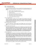
Figure 6.18-3 Endpoint SRAM Structure
6.18.5.8 Handling Transactions with USB Device Peripheral
User can use interrupt or polling USBD_INTSTS to monitor the USB transactions. When
transactions occur, USBD_INTSTS will be set by hardware and send an interrupt request to CPU
(if related interrupt enabled), or user can polling USBD_INTSTS to get these events without
interrupt. The following is the control flow with interrupt enabled.
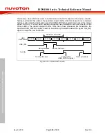
When USB host has requested data from a device controller, user needs to prepare related data in
the specified endpoint buffer in advance. After buffering the required data, user needs to write the
actual data length in the specified USBD_MXPLDx register. Once this register is written, the internal
signal “In_Rdy” will be asserted and the buffering data will be transmitted immediately after
receiving associated IN token from Host. Note that after transferring the specified data, the signal
“In_Rdy” will de-assert automatically by hardware.
USB_IRQ
In_Rdy
Data In
SETUP PID Data Setup
ACK PID
IN PID
NAK PID
IN PID
Data 0/1
ACK PID
USB
Bus Packets
Setup Received
Setup Handled by Firmware
Set by Hardware
Clear by Firmware
Set by writing
USBD_MXPLDx
register
Clear by Hardware
Figure 6.18-4 Setup Transaction Followed by Data IN Transaction

