ISD94100 Series Technical Reference Manual
Sep 9, 2019
Page
347
of 928
Rev1.09
IS
D
9
410
0
S
ER
IE
S
T
E
C
HN
ICA
L
RE
F
E
RE
NCE
M
AN
U
AL
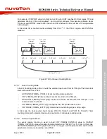
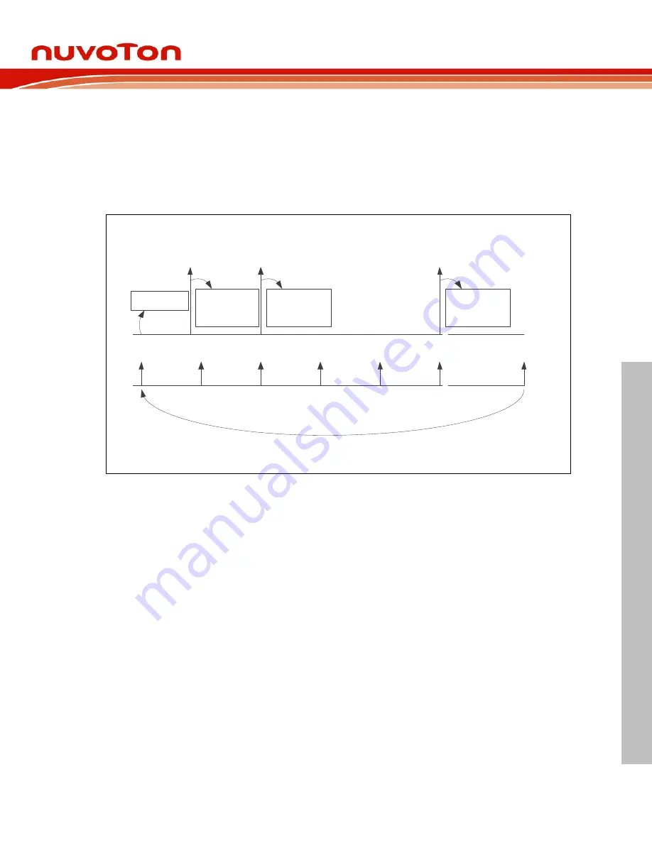
For example, if CMPDAT value is initially set as 80, when CNT reaches 80, timer raises TIF and
generates interrupt (if interrupt enabled), and counting continues. Now assume software clears
TIF and re-set CMPDAT value to 200, then when CNT reaches 200 timer will raise TIF and generate
interrupt again.
In this mode, timer counter counts endlessly from 0 to 2
24
-1, then from 0 again, until CNTEN is
disabled.
CNT = 0
Set
CMPDAT = 80
TIF = 1 and
Interrupt
Generation
Clear TIF as 0
and Set
CMPDAT = 200
CNT from 2
24
-1 to 0
CNT = 100
CNT = 200
CNT = 300
CNT = 400
CNT = 500
CNT = 2
24
-1
TIF = 1 and
Interrupt
Generation
Clear TIF as 0
and Set
CMPDAT = 500
TIF = 1 and
Interrupt
Generation
Clear TIF as 0
and Set
CMPDAT = 80
Figure 6.7-8 Continuous Counting Mode
6.7.5.7
Event Counting Mode
In Event Counting mode, a timer counts the external input event from its TMx pin. The timer clock
source should be from PCLK.
-
EXTCNTEN (TIMERx_CTL[24]): Event counting mode enable bit.
-
CNT (TIMERx_CNT[23:0]): number of events occurred on the TMx pin.
-
ECNTSSEL (TIMERx_EXTCTL[16]): equals 0 to choose event source from TMx pin. ‘1’ is a
reserved value for this bit.
-
CNTDBEN (TIMERx_EXTCTL[7]): configures the TMx pin de-bounce value.
-
CNTPHASE (TIMERx_EXTCTL[0]): determine to count falling edge or rising edge
In this mode, the clock source should choose PCK0 for Time0/1, and PCK1 for Timer2/3. Timer
counting mode can be selected as one-shot, periodic or continuous counting mode.
6.7.5.8
External Capture Mode
The event capture function is used to load CNT (TIMERx_CNT[23:0]) value to CAPDAT
(TIMERx_CAP[23:0]) value while edge transition detected on TMx_EXT (x= 0~3) pin. In this mode,
CAPFUNCS (TIMERx_EXTCTL[4]) should be as 0 to trigger event capture function and the timer
peripheral clock source should be set as PCLK.

