ISD94100 Series Technical Reference Manual
Sep 9, 2019
Page
357
of 928
Rev1.09
IS
D
9
410
0
S
ER
IE
S
T
E
C
HN
ICA
L
RE
F
E
RE
NCE
M
AN
U
AL
Table 6.7.6-2 PWM Pulse Generation Event Priority in Down Count Type
Table 6.7.6-3 PWM Pulse Generation Event Priority in Up-Down Count Type
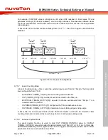
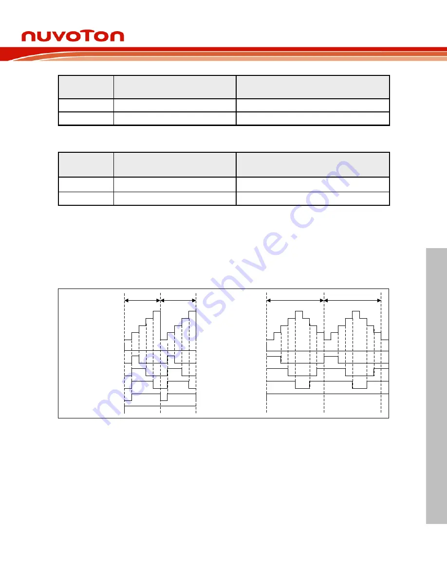
According to event priority limitation, PWM generator can support 0% and 100% duty cycle PWM
output waveform only in up count and up-down count type. Figure 6.7-23 is an example about PWM
duty cycle from 0% to 100% in up count type and up-down count type where PERIOD is 4 with
different CMP value.
0
1
2
3
4
3
2
1
0
1
2
3
4
3
2
1
0
PWM period
PWM period
0
1
2
3
4
0
1
2
3
4
CMPU = L
Zero = H
PWM period
PWM period
CMPU = L
CMPD = H
CMPDAT=0, 0% Duty
CMPDAT=1, 25% Duty
CMPDAT=2, 50% Duty
CMPDAT=3, 75% Duty
CMPDAT=4, 100% Duty
CMPDAT=0, 0% Duty
CMPDAT=1, 20% Duty
CMPDAT=2, 40% Duty
CMPDAT=3, 60% Duty
CMPDAT=4, 80% Duty
CMPDAT>4,100% Duty
Figure 6.7-23 PWM 0% to 100% Duty Cycle in Up Count Type and Up-Down Count Type
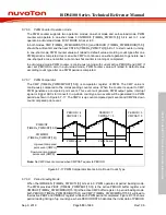
6.7.6.11 PWM Output Mode
The PWM supports two output modes: independent mode which may be applied to DC motor
system, complementary mode with dead-time insertion which may be used in the application of AC
induction motor and permanent magnet synchronous motor.
6.7.6.12 Independent mode
When OUTMODE (TIMERx_PWMCTL[16]) bit is set to 0, PWM output operates in independent
mode. In this mode, both PWMx_CH0 and PWMx_CH1 can output the same waveform as shown
Priority
Period and CMPD point event
(CMP = PERIOD)
PWM output
1 (High)
Compare down event
High
2 (Low)
Period event
Low
Priority
CMPU And CMPU Point Event
(CMP = PERIOD)
PWM Output
1 (High)
Compare down event
High
2 (Low)
Compare up event
Low


