ISD94100 Series Technical Reference Manual
Sep 9, 2019
Page
359
of 928
Rev1.09
IS
D
9
410
0
S
ER
IE
S
T
E
C
HN
ICA
L
RE
F
E
RE
NCE
M
AN
U
AL
Dead-Time
12-bits
Dead-Time
12-bits
DTEN
(TIMERx_PWMDTCTL[16])
Independent Mode
Three Steps
Independent Mode
Three Steps
DTCNT
(TIMERx_PWMDTCTL[11:0])
Pulse
Generator
TMx
(PWMx_CH0)
TMx_EXT
(PWMx_CH1)
complementary
control
dead-time insertion control
DTCKSEL
(TIMERx_PWMDTCTL[24])
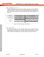
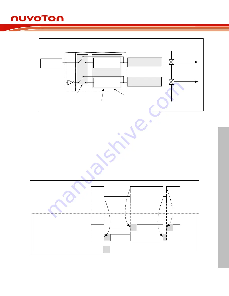
Figure 6.7-27 PWMx_CH0 and PWMx_CH1 Output Control in Complementary Mode
6.7.6.15 Dead-Time Insertion Control
In the complementary application, the complement channels may drive the external devices like
power switches. The dead-time generator inserts a low level interval between complementary
outputs PWMx_CH0 and PWMx_CH1 as shown in Figure 6.7-28. User sets DTEN
(TIMERx_PWMDTCTL[16]) bit to enable dead-time control function, DTCNT
(TIMERx_PWMDTCTL[11:0]) and DTCKSEL (TIMERx_PWMDTCTL[24]) to control dead-time
interval. The dead-time interval can be calculated from the following formula:
Dead-time interval = (DTCNT + 1) * TMRx_PWMCLK period, if DTCKSEL is 0
Dead-time interval = (DTCNT + 1) * TMRx_PWMCLK * ( 1) period, if DTCKSEL is 1
PWMx_CH0
PWMx_CH1
PWMx_CH0
PWMx_CH1
Dead-Time Interval
without Dead-Time:
with Dead-Time:
Figure 6.7-28 Dead-Time Insertion


