ISD94100 Series Technical Reference Manual
Sep 9, 2019
Page
361
of 928
Rev1.09
IS
D
9
410
0
S
ER
IE
S
T
E
C
HN
ICA
L
RE
F
E
RE
NCE
M
AN
U
AL
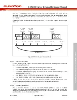
PWMx_CH0
PWMx_CH1
PWMx_CH0
PWMx_CH1
(PINV0=0)
(PINV1=0)
PWMx_CH0
PWMx_CH1
PWMx_CH0
PWMx_CH1
PWMx_CH0
PWMx_CH1
(PINV0=1)
(PINV1=0)
(PINV0=0)
(PINV1=1)
(PINV0=1)
(PINV1=1)
Initial State PWM Starts
dead-time insertion
Note1
:
Note2
: PINV0/PIV1, it controls the output polar inverse
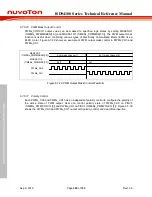
Figure 6.7-30 PWMx_CH0 and PWMx_CH1 Polarity Control with Dead-Time Insertion
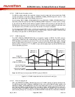
6.7.6.18 PWM Interrupt Generator
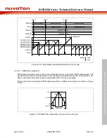
There are independent interrupts for each PWM as shown in Figure 6.7-31.
The PWM interrupt (PWMx_INT) comes from PWM complementary pair events. The counter can
generate the zero point interrupt flag ZIF (TIMERx_PWMINTSTS0[0]) and the period point interrupt
flag PIF (TIMERx_PWMINTSTS0[1]). When counter equals to the comparator value stored in CMP
(TIMERx_PWMCMPDAT[15:0]), the different interrupt flags will be triggered depending on the
counting direction. If counter and CMP matched occurs at up-count direction, the comparator up
interrupt flag CMPUIF (TIMERx_PWMINTSTS0[2]) is set and if matched at down-count direction,
the comparator down interrupt flag CMPDIF (TIMERx_PWMINTSTS0[3]) is set. If the
corresponding interrupt enable bits are set, the interrupt trigger events will also generates interrupt
signals.

