ISD94100 Series Technical Reference Manual
Sep 9, 2019
Page
416
of 928
Rev1.09
IS
D
9
410
0
S
ER
IE
S
T
E
C
HN
ICA
L
RE
F
E
RE
NCE
M
AN
U
AL
CMPDAT DATA0
CMPDAT DATA1
PERIOD DATA0
PERIOD DATA1
PERIOD DATA3
CNT
Load Window
PERIOD DATA2
Write
Load
Note:
CMPU
CMPDAT
PERIOD
PERIOD DATA0
PERIOD DATA1
CMPDAT DATA1
PBUF
PERIOD DATA0
PERIOD DATA1
CMPBUF
CMPDAT DATA1
PERIOD DATA 3
PERIOD DATA2
CMPDAT DATA0
PERIOD DATA2
PERIOD DATA3
point 1
point 2
point 3
point 4
point 5
point 6
point 7
point 8 point 9
CLKPSC DATA0
CLKPSC DATA3
CLKPSC DATA1
CLKPSC DATA2
CLKPSC DATA0
CLKPSC DATA3
CLKPSC DATA1
CLKPSC DATA2
CLKPSC
CLKPSCBUF
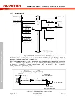
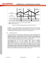
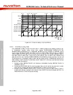
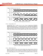
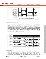
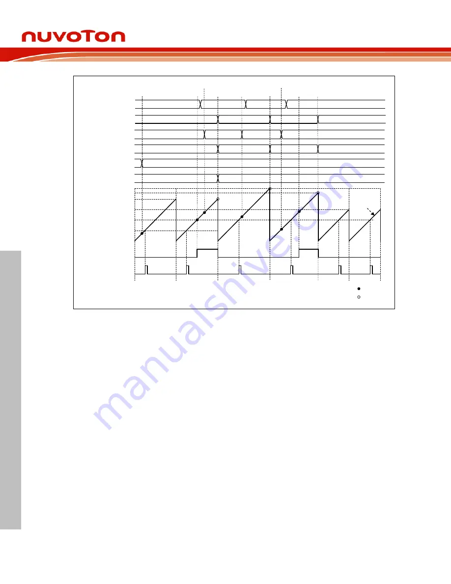
Figure 6.8-15 Window Loading in Up-Count Mode
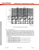
6.8.5.11 Center Loading Mode
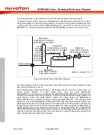
When the CTRLDn (PWM_CTL0[5:0]) bit is set to 1 and PWM counter is set to up-down count type,
CNTTYPEn (PWM_CTL1[2n+1:2n], n = 0,1..5) is 0x2, PWM operates at center loading mode. In
center loading mode, CMP(PWM_CMPDATn[15:0]) will load to active CMPBUF register in center
of each period, that is, counter counts to PERIOD. CLKPSC(PWM_CLKPSCn_m[11:0]) and
PERIOD(PWM_PERIODn[15:0]) will all load to their active CPSCBUF and PBUF registers while
each period is completed Center loading mode can work with window loading mode, the
CMP(PWM_CMPDATn[15:0]) will load to active CMPBUF register in center of each period , but it
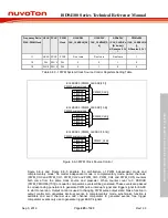
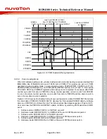
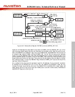
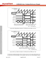
is valid only at the interval of load window. Figure 6.8-16 shows an example and its steps sequence
is described below.
1. Software writes CMPDAT DATA1 at point 1.
2. Hardware loads CMPDAT DATA1 to CMPBUF at center of PWM period at point 2.
3. Software writes PERIOD DATA1 at point 3.
4. Hardware loads PERIOD DATA1 to PBUF at the end of PWM period at point 4.
5. Software writes CMPDAT DATA2 at point 5.
6. Hardware loads CMPDAT DATA2 to CMPBUF at center of PWM period at point 6.
7. Software writes PERIOD DATA2 at point 7.
8. Hardware loads PERIOD DATA2 to PBUF at the end of PWM period at point 8.

