ISD94100 Series Technical Reference Manual
Sep 9, 2019
Page
418
of 928
Rev1.09
IS
D
9
410
0
S
ER
IE
S
T
E
C
HN
ICA
L
RE
F
E
RE
NCE
M
AN
U
AL
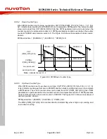
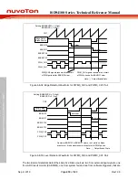
PERIOD DATA1
CMPDAT DATA3
PERIOD DATA0
CMPDAT DATA0
One-shot
Continuous one-
shot
PWM OUT
CNT
Write
Load
Note:
point 1 point 2 point 3 point 4 point 5
point 6
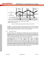
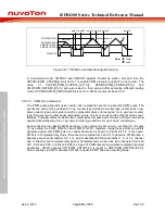
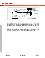
Figure 6.8-17 PWM One-shot Mode Output Waveform
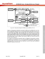
In Auto-reload mode, CMPDAT and PERIOD registers should be written first and then the
CNTENn(PWM_CNTEN[n]) bit is set to 1 to enable PWM prescaler and start to run counter. The
value of CLKPSC(PWM_CLKPSCn_m[11:0]), PERIOD(PWM_PERIODn[15:0]) and
CMP(PWM_CMPDATn[15:0]) will auto reload to their active buffer according different loading
mode. If PERIOD(PWM_PERIODn[15:0]) is set to 0, PWM counter will be set to 0.
6.8.5.13 PWM Pulse Generator
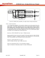
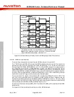
The PWM pulse generator uses counter and comparator events to generate PWM pulse. The
events are: zero point, period point in up counter type and down counter type, center point in up-
down counter type and counter equal to comparator point in three types. As to up-down counter
type, there are two counter equal comparator points, one at up count and the other at down count.
Besides, Complementary mode has two comparators compared with counter, and thus comparing
equal points will become four in up-down counter type and two for up or down counter type.
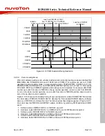
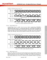
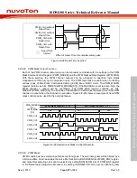
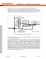
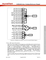
Each event point can decide PWM waveform to do nothing (X), set Low (L), set High (H) or toggle
(T) by setting the PWM_WGCTL0 and PWM_WGCTL1 registers. Using these points can easily
generate asymmetric PWM pulse or variant waveform as shown in Figure 6.8-18. In the figure,
PWM is in complementary mode, there are two comparators n and m to generate PWM pulse. n
denotes even channel number 0, 2, or 4, and m denotes odd channel number 1, 3, or 5. n channel
and m channel are complementary paired. Complementary mode uses two channels (CH0 and
CH1, CH2 and CH3, or CH4 and CH5) as a pair of PWM outputs to generate complement paired
waveforms. CMPU denotes CNT(PWM_CNTn[15:0]) is equal to CMP(PWM_CMPDATn[15:0])
when counting up. CMPD denotes CNT bits is equal to CMP bits when counting down.

