ISD94100 Series Technical Reference Manual
Sep 9, 2019
Page
421
of 928
Rev1.09
IS
D
9
410
0
S
ER
IE
S
T
E
C
HN
ICA
L
RE
F
E
RE
NCE
M
AN
U
AL
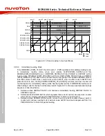
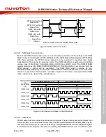
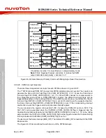
PWM_CH2
PWM_CH0
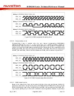
Setting:
OUTMODE0 (PWM_CTL1[24]) = 0x0
PWM_CH1
PWM_CH3
PWM_CH4
PWM_CH5
Setting:
OUTMODE2 (PWM_CTL1[25]) = 0x0
Setting:
OUTMODE4 (PWM_CTL1[26]) = 0x0
Figure 6.8-20 PWM Independent Mode Waveform
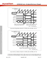
6.8.5.16 Complementary mode
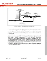
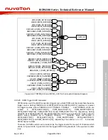
Complementary mode is enabled when the pair channel corresponding PWMMODEn
(PWM_CTL1[26:24]) bit set to 1. In this mode there are 3 PWM generators utilized for
complementary mode, with total of 3 PWM output paired pins in this module. In Complementary
modes, the internal odd PWM signal must always be the complement of the corresponding even
PWM signal. PWM_CH1 will be the complement of PWM_CH0. PWM_CH3 will be the complement
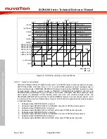
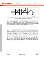
of PWM_CH2 and PWM_CH5 will be the complement of PWM_CH4 as shown in Figure 6.8-21.
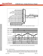
PWM_CH2
PWM_CH0
Setting:
OUTMODE0 (PWM_CTL1[24]) = 0x1
PWM_CH1
PWM_CH3
PWM_CH4
PWM_CH5
Setting:
OUTMODE2 (PWM_CTL1[25]) = 0x1
Setting:
OUTMODE4 (PWM_CTL1[26]) = 0x1
Figure 6.8-21 PWM Complementary Mode Waveform
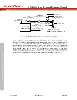
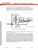
6.8.5.17 PWM Output Function
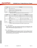
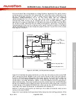
Based on the output mode, there are two output functions: group and synchronous functions for
advanced output control. Group function, forces the PWM_CH2 and PWM_CH4 synchronous with
PWM_CH0 generator and forces the PWM_CH3 and PWM_CH5 synchronous with PWM_CH1,
may simplify updating duty control in DC and BLDC motor applications. Besides, Synchronous

