ISD94100 Series Technical Reference Manual
Sep 9, 2019
Page
427
of 928
Rev1.09
IS
D
9
410
0
S
ER
IE
S
T
E
C
HN
ICA
L
RE
F
E
RE
NCE
M
AN
U
AL
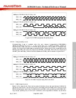
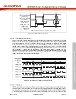
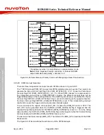
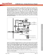
PWM_CH0 without
Dead-Time
PWM_CH1 without
Dead-Time
PWM_CH0 with
Dead-Time
PWM_CH1 with
Dead-Time
Dead-Time
Interval
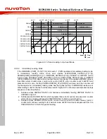
Effect of Dead-Time for complementary pairs
Figure 6.8-28 Dead-Time Insertion
6.8.5.22 PWM Mask Output Function
Each of the PWM channel output value can be manually overridden with the settings in the PWM
Mask Enable Control Register (PWM_MSKEN) and the PWM Masked Data Register (PWM_MSK)
With these settings, the PWM channel outputs can be assigned to specified logic states
independent of the duty cycle comparison units. The PWM mask bits are useful when controlling
various types of Electrically Commutated Motor (ECM) like a BLDC motor. The PWM_MSKEN
register contains six bits, MSKENn(PWM_MSKEN[5:0]). If the MASKENn is set to active-high, the
PWM channel n output will be overridden. The PWM_MSK register contains six bits,
MSKDATn(PWM_MSK[5:0]). The bit value of the MSKDATn determines the state value of the PWM
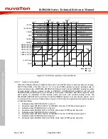
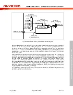
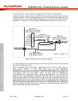
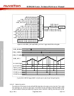
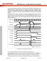
channel n output when the channel is overridden. Figure 6.8-29 shows an example of how PWM
mask control can be used for the override feature.
PWM_CH2
PWM_CH0
PWM_MSK
[5:0]
0x8
0x11
0x5
PWM_MSKEN
[5:0]
PWM_CH1
PWM_CH3
0x2A (Mask channel 1, 3, 5)
0x15 (Mask channel 0, 2, 4)
PWM_CH4
PWM_CH5
Figure 6.8-29 Illustration of Mask Control Waveform
6.8.5.23 PWM Brake
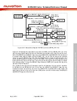
PWM module has two external input brake control signals. The external signals will be filtered by a
3-bit noise filter. User can enable the noise filter function by BRKxNFEN bits of PWM_BNF register,
and noise filter sampling clock can be selected by setting BRKxNFSEL bits of PWM_BNF register
to fit different noise properties. Moreover, by setting the BRKxFCNT bits, user can define by how

