ISD94100 Series Technical Reference Manual
Sep 9, 2019
Page
432
of 928
Rev1.09
IS
D
9
410
0
S
ER
IE
S
T
E
C
HN
ICA
L
RE
F
E
RE
NCE
M
AN
U
AL
PWM_WGCTL0
PWM_WGCTL1
PWM_CH0
PWM_CH1
off
on
on
off
off
off
on
off
(PINV0=0)
(PINV1=0)
Dead-time insertion; It is only effective in complementary mode
Note
: PINVx: Negative Polarity control bits; It controls the PWM
output initial state and polarity, x denotes 0 or 1.
PWM_CH0
PWM_CH1
PWM_CH0
PWM_CH1
PWM_CH0
PWM_CH1
(PINV0=1)
(PINV1=0)
(PINV0=0)
(PINV1=1)
(PINV0=1)
(PINV1=1)
Initial State
PWM Starts
on
off
off
on
off
off
on
off
off
on
on
off
off
off
on
off
off
off
on
off
on
off
off
on
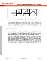
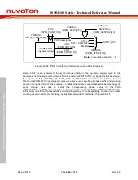
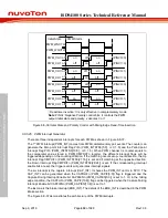
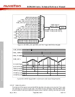
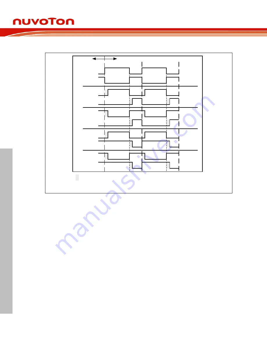
Figure 6.8-36 Initial State and Polarity Control with Rising Edge Dead-Time Insertion
6.8.5.25 PWM Interrupt Generator
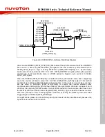
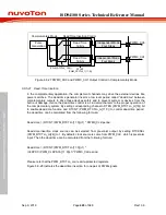
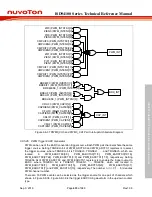
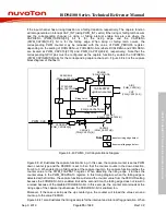
There are three independent interrupts for each PWM as shown in Figure 6.8-37.
The 1
st
PWM interrupt (PWM_INT) comes from PWM complementary pair events. The counter can
generate the Zero point Interrupt Flag ZIFn (PWM_INTSTS0[5:0] , n=0,1..5) and the Period point
Interrupt Flag PIFn (PWM_INTSTS0[13:8] , n=0,1..5). When PWM channel n’s counter equals to
the comparator value stored in PWM_CMPDATn register, the different interrupt flags will be
triggered depending on the counting direction. If the matching occurs at up–count direction, the Up
Interrupt Flag CMPUIFn (PWM_INTSTS0[21:16]) is set and if matching at the opposite direction,
the Down Interrupt Flag CMPDIFn (PWM_INTSTS0[29:24]) is set. If the corresponding interrupt
enable bits are set, the trigger events will generates interrupt signals.
The 2
nd
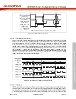
interrupt is the capture interrupt (CAP_INT). It shares the PWM_INT vector in NVIC. The
CAP_INT can be generated when the CAPRLIFn (PWM_CAPIF[5:0]) flag is triggered and the
Capture Rising Interrupt Enable bit CAPRIENn (PWM_CAPIEN[5:0]) is set to 1. Or in the falling
edge condition, the CAPFLIFn (PWM_CAPIF[13:8]) flag can be triggered when the Capture Falling
Interrupt Enable bit CAPFIENn (PWM_CAPIEN[13:8]) is set to 1.
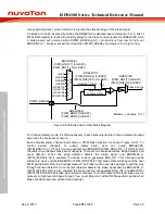
The last one is the brake interrupt (BRK_INT). The details of the BRK_INT is described in the PWM
Brake section.
The Figure 6.8-37 demonstrates the architecture of the PWM interrupts.

