ISD94100 Series Technical Reference Manual
Sep 9, 2019
Page
567
of 928
Rev1.09
IS
D
9
410
0
S
ER
IE
S
T
E
C
HN
ICA
L
RE
F
E
RE
NCE
M
AN
U
AL
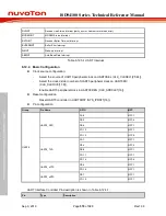
Incoming Data Wake-up
√
RX FIFO reached threshold
Wake-up
√
RS-485 Address Match (AAD
mode) Wake-up
√
Auto-Baud Rate Measurement
√
STOP Bit Length
1, 1.5, 2 bit
Word Length
5, 6, 7, 8 bits
Even / Odd Parity
√
Stick Bit
√
√
= Supported
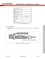
Table 6.12.2-1 UART Feature
6.12.3 Block Diagram
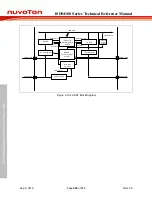
The UART clock control and block diagram are shown in Figure 6.12-1 and Figure 6.12-2
respectively.
11
10
01
00
4~24 MHz HXT
PLL FOUT
32.768kHz LXT
HIRC
UART0SEL (CLK_CLKSEL1[25:24])
UART0DIV (CLK_CLKDIV0[11:8])
UART0CKEN (CLK_APBCLK0[16]
UART0_CLK
Note:
Before clock switching, both the pre-selected and
newly selected clock sources must be turned on and stable.
1/(U1)
Figure 6.12-1 UART Clock Control Diagram


