ISD94100 Series Technical Reference Manual
Sep 9, 2019
Page
570
of 928
Rev1.09
IS
D
9
410
0
S
ER
IE
S
T
E
C
HN
ICA
L
RE
F
E
RE
NCE
M
AN
U
AL
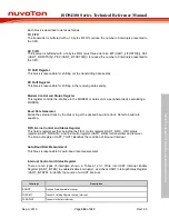
RLSINT
Receive Line Status Interrupt (parity error or frame error or break error).
MODEMINT
MODEM Status Interrupt.
RXTOINT
Receiver Buffer Time-out Interrupt.
BUFERRINT
Buffer Error Interrupt.
WKINT
Wake-up Interrupt.
ABRINT
Auto-Baud Rate Interrupt.
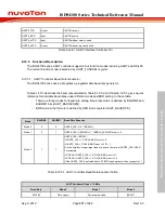
Table 6.12.3-1 UART Interrupt
6.12.4 Basic Configuration
Clock source configuration
–
Select the source of UART0 peripheral clock on UART0SEL (CLK_CLKSEL1[25:24]).
–
Select the clock divider number of UART0 peripheral clock on UART0DIV
(CLK_CLKDIV0[11:8]).
–
Enable UART0 peripheral clock in UART0CKEN (CLK_APBCLK1[16]).
Reset configuration
–
Reset UART0 controller in UART0RST (SYS_IPRST1[16]).
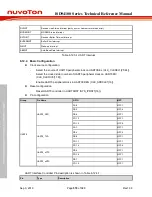
Pin configuration
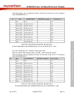
Group
Pin Name
GPIO
MFP
UART0
UART0_RXD
PA.8
MFP1
PB.3
MFP4
PB.9
MFP1
PD.12
MFP1
PD.15
MFP4
UART0_TXD
PA.7
MFP1
PB.4
MFP4
PB.8
MFP1
PD.11
MFP1
PD.14
MFP4
UART0_nCTS
PB.4
MFP1
PD.14
MFP1
UART0_nRTS
PB.7
MFP1
PD.15
MFP1
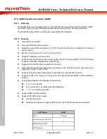
UART Interface Controller Pin description is shown in Table 6.12.4-1:
Pin
Type
Description

