ISD94100 Series Technical Reference Manual
Sep 9, 2019
Page
582
of 928
Rev1.09
IS
D
9
410
0
S
ER
IE
S
T
E
C
HN
ICA
L
RE
F
E
RE
NCE
M
AN
U
AL
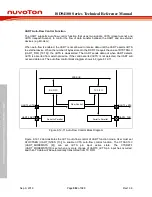
UART Auto-Flow Control Function
The UART supports auto-flow control function that uses two signals, nCTS (clear-to-send) and
nRTS (request-to-send), to control the flow of data transfer between the UART and an external
devices (e.g. Modem).
When auto-flow is enabled, the UART is not allowed to receive data until the UART asserts nRTS
to external device. When the number of bytes stored in the RX FIFO equals the value of RTSTRGLV
(UART_FIFO [19:16]), the nRTS is de-asserted. The UART sends data out when UART detects
nCTS is asserted from external device. If the valid asserted nCTS is not detected, the UART will
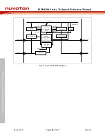
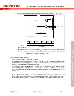
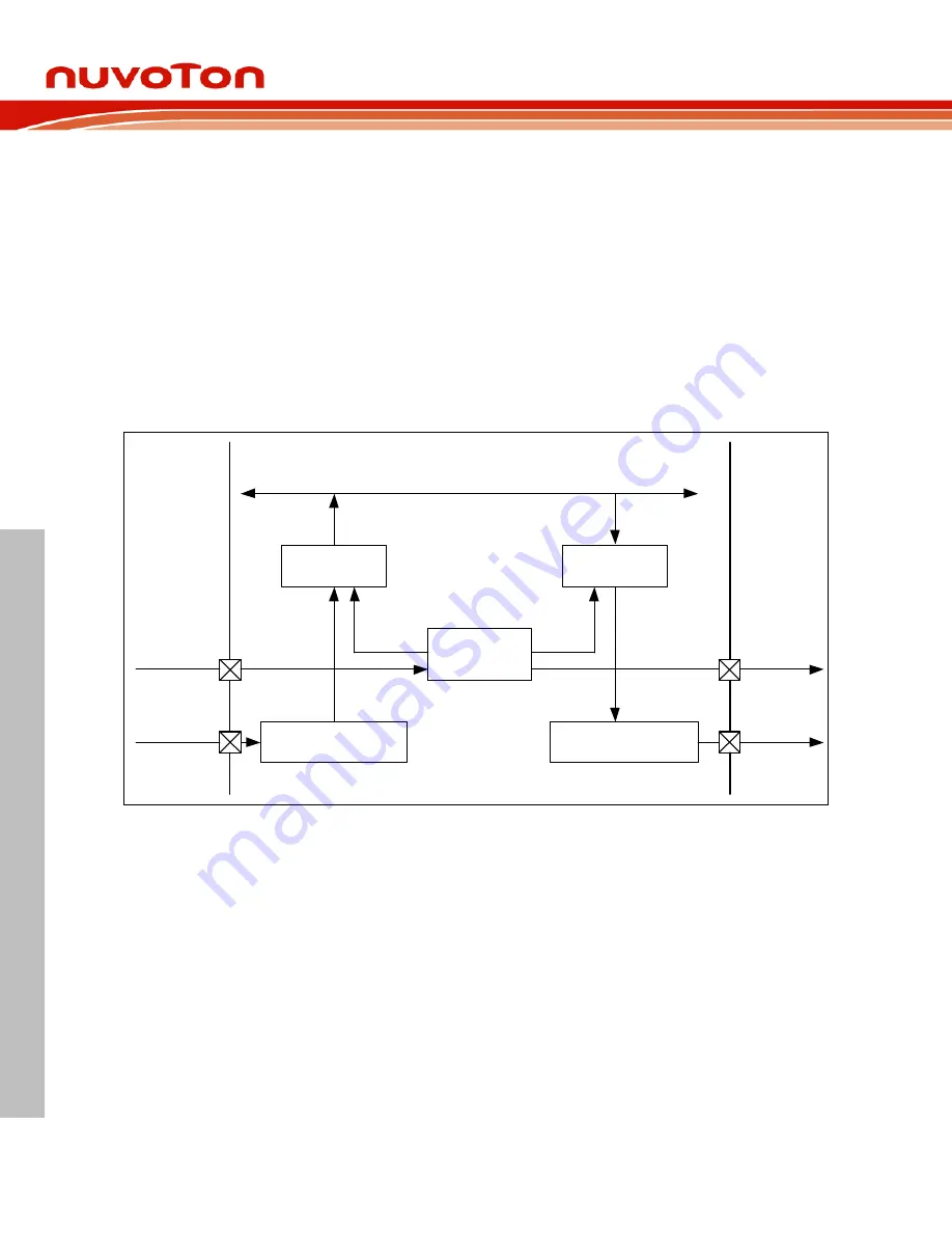
not send data out. The auto flow control block diagram shows in Figure 6.12-11.
APB BUS
RX FIFO
TX FIFO
Flow Control
Serial to Parallel
Serial to Parallel
UART0_nCTS
UART0_RXD
UART0_nRTS
UART0_TXD
Figure 6.12-11 Auto-Flow Control Block Diagram
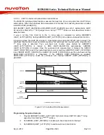
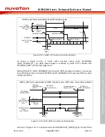
Figure 6.12-12 demonstrates the nCTS auto-flow control of UART function mode. User must set
ATOCTSEN (UART_INTEN [13]) to enable nCTS auto-flow control function. The CTSACTLV
(UART_MODEMSTS [8]) can set nCTS pin input active state. The CTSDETF
(UART_MODEMSTS[0]) is set when any state change of UART0_nCTS pin input has occurred,
and then TX data will be automatically transmitted from TX FIFO.

