ISD94100 Series Technical Reference Manual
Sep 9, 2019
Page
61
of 928
Rev1.09
IS
D
9
410
0
S
ER
IE
S
T
E
C
HN
ICA
L
RE
F
E
RE
NCE
M
AN
U
AL
6.2.6
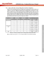
Brown-out Detector and Low Voltage Reset Controller Configuration
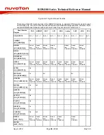
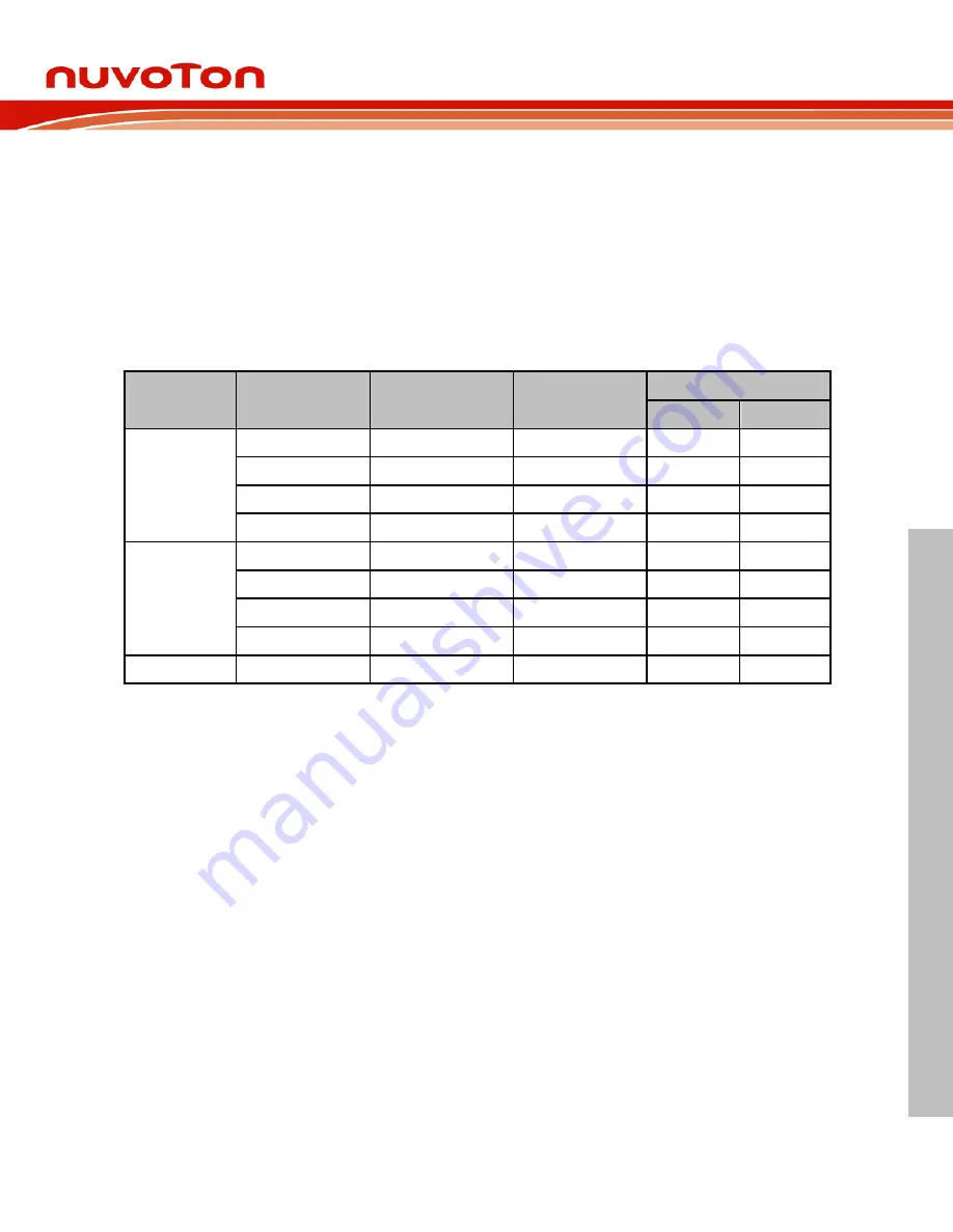
ISD94100 series is equipped with brown-out detector and low voltage reset controller function. Low
voltage reset controller is enabled by setting LVREN(SYS_BODCTL[7]) to 1. Brown-out detector is
enabled by setting both LVREN(SYS_BODCTL[7]) and BODEN(SYS_BODCTL[0]) to 1. Both
brown-out detector and low voltage reset controller also integrates low power mode function, the
low power mode is enabled by setting BODLPM(SYS_BODCTL[5]). When enable low power mode,
brown-out detector and low voltage reset controller will consume less power, but the detection
speed will become slow (The response time is about 13ms). When using brown-out detector and
low voltage reset controller, the LIRC must be turned on. In addition, the brown-out detector cannot
operate independently without enabled low voltage reset controller.
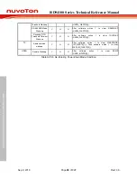
Power Mode
LVREN
(SYS_BODCTL[7])
BODEN
(SYS_BODCTL[0])
BODLPM
(SYS_BODCTL[5])
LVR / BOD Operation Mode
LVR
BOD
Normal / Idle / PD
0
X
X
Disabled
Disabled
1
0
X
Normal
Disabled
1
1
0
Normal
Normal
1
1
1
Low power
Low power
LLPD / SPD0 /
SPD1
0
X
X
Disabled
Disabled
1
0
X
Low power
Disabled
1
1
0
Normal
Normal
1
1
1
Low power
Low power
DPD
X
X
X
Disabled
Disabled
Table 6.2.6-1 Brown-out Detector and Low Voltage Reset Controller Effect Table
Note:
X means don’t care, write 1 or 0 to correspond register bit will not affect functionality.


