ISD94100 Series Technical Reference Manual
Sep 9, 2019
Page
645
of 928
Rev1.09
IS
D
9
410
0
S
ER
IE
S
T
E
C
HN
ICA
L
RE
F
E
RE
NCE
M
AN
U
AL
Master Mode
Slave Mode
STATUS
Description
STATUS
Description
0x08
Start
0xA0
Slave Transmit Repeat Start or Stop
0x10
Master Repeat Start
0xA8
Slave Transmit Address ACK
0x18
Master Transmit Address ACK
0xB8
Slave Transmit Data ACK
0x20
Master Transmit Address NACK
0xC0
Slave Transmit Data NACK
0x28
Master Transmit Data ACK
0xC8
Slave Transmit Last Data ACK
0x30
Master Transmit Data NACK
0x60
Slave Receive Address ACK
0x38
Master Arbitration Lost
0x68
Slave Receive Arbitration Lost
0x40
Master Receive Address ACK
0x80
Slave Receive Data ACK
0x48
Master Receive Address NACK
0x88
Slave Receive Data NACK
0x50
Master Receive Data ACK
0x70
GC mode Address ACK
0x58
Master Receive Data NACK
0x78
GC mode Arbitration Lost
0x00
Bus error
0x90
GC mode Data ACK
0x98
GC mode Data NACK
0xB0
Address Transmit Arbitration Lost
0xF0
If the BMDEN =1 and the ACKMEN bit is enabled, the information of I2C_STATUS will be fixed as 0xF0 in slave
receive condition.
0xF8
Bus Released
Note:
Status “0xF8” exists in both master/slave modes, and it won’t raise interrupt.
Table 6.13.5-3 I
2
C Status Code Description
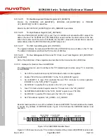
6.13.5.4.6
Clock Baud Rate Bits (I2C_CLKDIV)
The data baud rate of I
2
C is determines by DIVIDER(I2C_CLKDIV [7:0] )register when I
2
C is in
Master Mode, and it is not necessary in a Slave mode. In the Slave mode, I
2
C will automatically
synchronize it with any clock frequency from master I
2
C device. In the slave mode, system clock
frequency should greater than I
2
C bus maximum clock 20 times.
The data baud rate of I
2
C setting is Data Baud Rate of I
2
C = (system clock) / (4x (I2C_CLKDIV [7:0]
+1)). If system clock = 16 MHz, the I2C_CLKDIV [7:0] = 40 (28H), the data baud rate of I
2
C = 16
MHz/ (4x (40 +1)) = 97.5 Kbits/sec.
6.13.5.4.7
Time-out Control Register (I2C_TOCTL)
There is a 14-bit time-out counter which can be used to deal with the I
2
C bus hang-up. If the time-
out counter is enabled, the counter starts up counting until it overflows (TOIF=1) and generates I
2
C
interrupt to CPU or stops counting by clearing TOCEN to 0. When time-out counter is enabled,
writing 1 to the SI flag will reset counter and re-start up counting after SI is cleared. If I
2
C bus hangs
up, it causes the I2C_STATUS and flag SI are not updated for a period, the 14-bit time-out counter
may overflow and acknowledge CPU the I
2
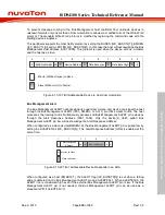
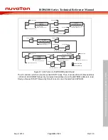
C interrupt. Refer to the Figure 6.13-27 for the 14-bit

