ISD94100 Series Technical Reference Manual
Sep 9, 2019
Page
756
of 928
Rev1.09
IS
D
9
410
0
S
ER
IE
S
T
E
C
HN
ICA
L
RE
F
E
RE
NCE
M
AN
U
AL
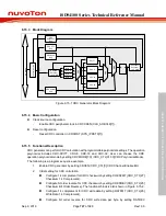
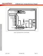
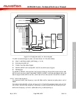
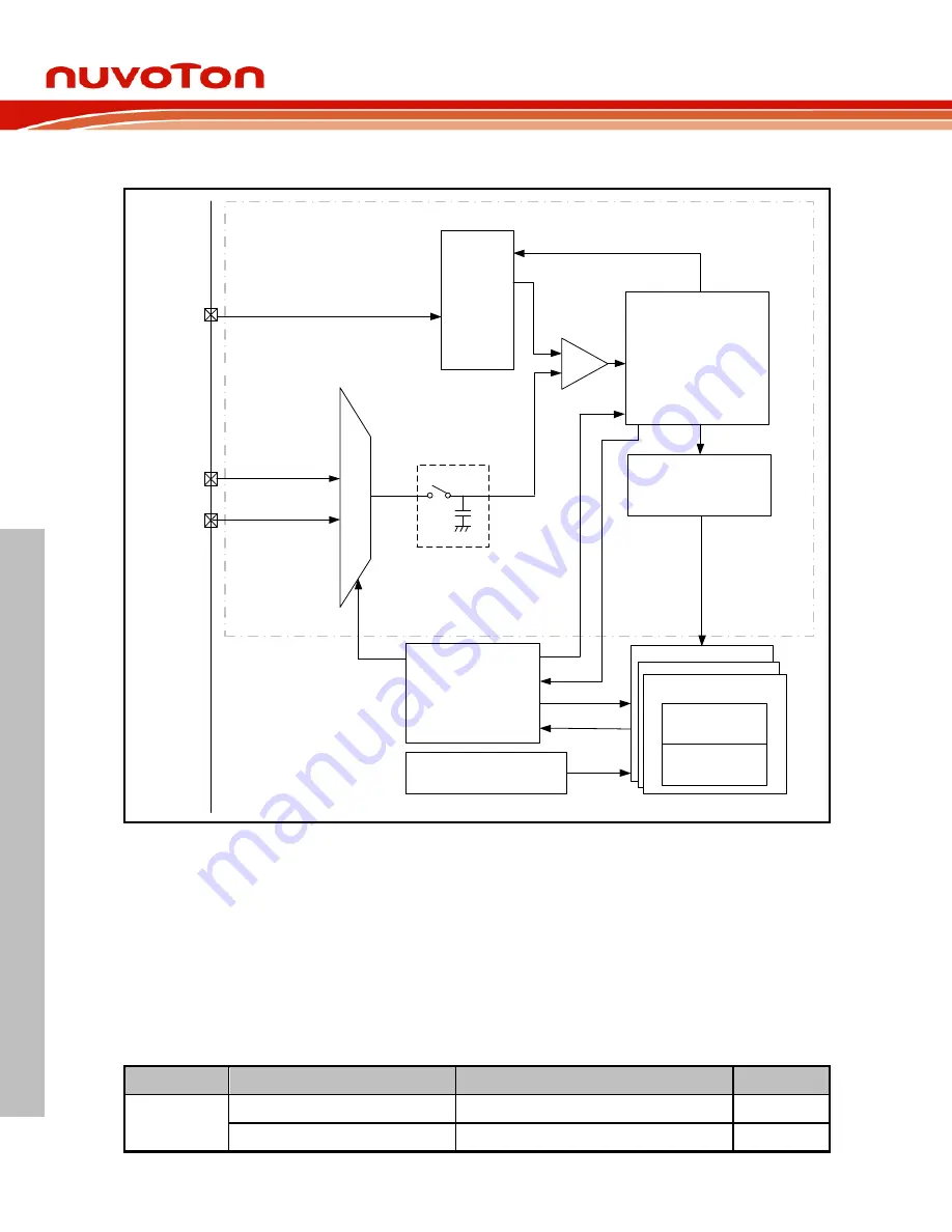
6.16.3 Block Diagram
12-bit DAC
Analog Control Logics
Successive
Approximations Register
+
-
Digatal Control Logics
&
ADC Clock Generator
...
EADC0_CH0
EADC0_CH12
13
to
1
Analog MUX
Sample and Hold
Comparator
ADC
_
FINISH
A/D result [11:0]
Analog Macro
ADC
_
START
&
ADC
_
CLK
CHSEL (EADC_SCTLn[4:0])
VALID & OVERRUN
User write, EADC0_ST input,
ADC interrupt, Timer0~3,
PWM triggers
Trigger
AV
DD
V
REF
A/D Sample Module 12
A/D Sample Module 0
...
Result Register
(EADC_DAT0)
Control Register
(EADC_SCTL0)
Figure 6.16-1 ADC Converter Block Diagram
6.16.4 Basic Configuration
Clock source configuration
–
Select the clock divider number in EADCDIV (CLK_CLKDIV0[23:16]).
–
Enable EADC peripheral clock in EADCCKEN (CLK_APBCLK0[28]).
Reset configuration
–
Reset EADC controller in ADCRST (EADC_CTL[1]).
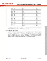
Pin configuration
Group
Pin Name
GPIO
MFP
EADC0
EADC0_CH0
PA.0
MFP2
EADC0_CH1
PA.1
MFP2


