ISD94100 Series Technical Reference Manual
Sep 9, 2019
Page
760
of 928
Rev1.09
IS
D
9
410
0
S
ER
IE
S
T
E
C
HN
ICA
L
RE
F
E
RE
NCE
M
AN
U
AL
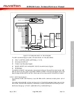
EADC
1/(1)
PCLK1
EADCCKEN
(CLK_APBCLK0[28])
EADCDIV (CLK_CLKDIV0[23:16])
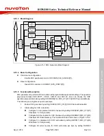
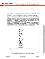
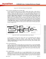
Figure 6.16-4 EADC Clock Control
6.16.5.2 ADC
Software
Trigger Mode
When a ADC conversion is performed on the sample module specified single channel, the
operations are as follows:
1. ADC conversion is started when the SWTRGn (EADC_SWTRG[n], n=0~12) is set to 1 by user
or other trigger inputs.
2. When ADC conversion is finished, the 12-bit result is stored in the ADC data register
EADC_DATn (n=0~12) corresponding to the sample module.
3. On completion of conversion, the ADIFn (EADC_STATUS2[3:0], n=0~3) is set to 1 and ADC
interrupt (ADINTn, n=0~3) is requested if the ADCIENn (EADC_CTL[5:2], n=0~3) bit is set to
1.
4. The SWTRGn (n=0~12) bit remains 1 during ADC conversion. When ADC conversion ends,
the SWTRGn (n=0~12) bit is automatically cleared to 0 and the ADC converter will do another
pending conversion.
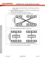
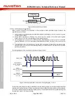
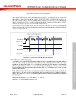
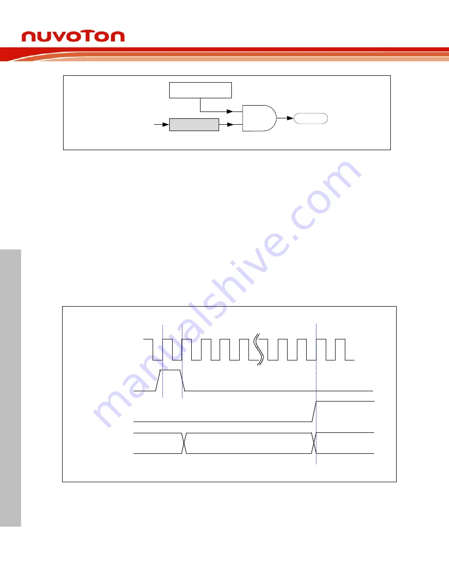
The timing diagram of a conversion is shown as Figure 6.16-5
Write
SWTRG
(EADC_SWTRG
[n],
n=0~12)
ADIFn
(
EADC_STATUS2
[n],
n=0~3)
RSLT
RESULT
(EADC_DATn[15:0],
n=0~12)
ADC_CLK
Figure 6.16-5 Example ADC Conversion Timing Diagram, n=0~12
If more than one sample module is enabled to convert analog single, the sample module specified
channel with highest priority is firstly converted and other enabled sample module will be pended.
The lower number sample module has higher priority. The sample module 0 is highest priority and
the sample module 12 is lowest priority.


