ISD94100 Series Technical Reference Manual
Sep 9, 2019
Page
764
of 928
Rev1.09
IS
D
9
410
0
S
ER
IE
S
T
E
C
HN
ICA
L
RE
F
E
RE
NCE
M
AN
U
AL
Delay
time
Delay
time
Starts A/D
converting
Starts A/D
converting
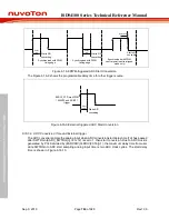
Synchronized with PWM
rising edge
Synchronized with PWM
falling edge
Starts A/D
converting
Synchronized with PWM
central point (centre-aligned
mode only)
Delay time
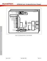
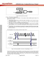
Figure 6.16-8 PWM-triggered ADC Start Conversion
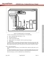
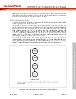
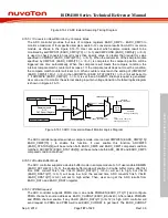
The Figure 6.16-9 shows the programmable delay time for other trigger source.
Delay
time
Starts A/D
converting
EADC0_ST/Timer/PWM
/ ADINT0 and ADINT1
trigger
Figure 6.16-9 External triggered ADC Start Conversion
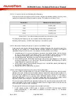
6.16.5.9 ADC Conversion Time
and External trigger
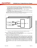
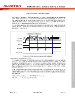
The ADC converter sample the analog input when ADC conversion start delay time (Td) has passed
after SWTRGn (EADC_SWTRG[n], n=0~12) is set to 1, then start conversion. Due to ADC clock is
generated by PCLK divided by (EADCDIV(CLKDIV[23:16])+1), the maximum delay time from user
write SWTRGn to ADC start sampling analog input time is two ADC clock cycles. The start delay
time is shown in Figure 6.16-10.

