ISD94100 Series Technical Reference Manual
Sep 9, 2019
Page
804
of 928
Rev1.09
IS
D
9
410
0
S
ER
IE
S
T
E
C
HN
ICA
L
RE
F
E
RE
NCE
M
AN
U
AL
I
2
S
Slave
I2S_MCLK
IS2_BCLK
I2S_LRCLK
I2S_DO
I2S_DI
Master
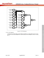
Figure 6.17-4 Slave mode Interface Block Diagram
6.17.5.3 I
2
S Operation
The I
2
S controller supports MSB-justified, LSB-justified, and I
2
S Philips standard data format. The
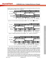
I2S_LRCLK signal indicates which audio channel is in transferring. The bit count of an audio
channel is defined by CHWIDTH (I2S_CTL0[29:28]), and the bit-width of data word in an audio
channel is determined by DATWIDTH (I2S_CTL0[5:4]). If CHWIDTH (I2S_CTL0[29:28]) is less than
DATWIDTH (I2S_CTL0[5:4]), the hardware will set the channel bit-width to be same as data bit-
width. However, there will be redundant zero bits in each audio channel if CHWIDTH
(I2S_CTL0[29:28]) is greater than DATWIDTH (I2S_CTL0[5:4]).
Data Word
I2S_BCLK
I2S_LRCLK
I2S_DI /
I2S_DO
Data Word
Data Word
Channel width
Channel width
Left channel of frame N
Right channel of frame N
Frame N+1
Figure 6.17-5 I
2
S Channel Width and Data Width (CHWIDTH
≦
DATWIDTH)
Data Word
I2S_BCLK
I2S_LRCLK
I2S_DI /
I2S_DO
Data Word
Data Word
Redundant
zero pad
Redundant
zero pad
Data width
Channel width
Data width
Channel width
Figure 6.17-6 I
2
S Channel Width and Data Width (CHWIDTH > DATWIDTH)
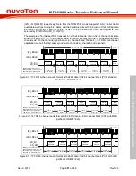
The transferring data sequence is always started from the MSB (most significance bit) to the LSB
(least significance bit). As the Figure 6.17-7, transmitting data are read at rising edge of I2S_BCLK
and sent out at falling edge of I2S_BCLK in I
2
S protocol. In I
2
S data format, the MSB is sent and
latched at the next falling edge of I2S_BCLK cycle after the transition of I2S_LRCLK. In MSB
justified data format, the I2S_LRCLK changes the polarity at the transmitting of the first data bit
(MSB) in each audio channel. In LSB justified data format, the LSB is sent and latched at the last

