ISD94100 Series Technical Reference Manual
Sep 9, 2019
Page
879
of 928
Rev1.09
IS
D
9
410
0
S
ER
IE
S
T
E
C
HN
ICA
L
RE
F
E
RE
NCE
M
AN
U
AL
6.20 Voice Active Detection (VAD)
6.20.1 Overview
The Voice Active Detection (VAD) analyses the PCM data from DMIC channel 0, and it consists of
a SINC filter, a biquad filter and a VAD module. The idea of the VAD is to calculate the short term
signal power and long term signal power of the input signal, and then compare the short term power
with the short term power threshold. Moreover, the deviation of the short term power and long term
power can be calculated and compared with the threshold deviation. Based on these two results,
which can determine if the input signal is voice or not.
VAD can be active during idle mode and therefore provide lowest power operation, compared with
a software based implementation.
6.20.2 Features
Configuration detect levels.
Supports idle mode wake-up function.
Supports auto switch DMIC path when CPU wake-up by VAD.
Generates interrupt requests when voice detected.
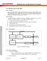
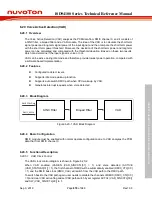
6.20.3 Block Diagram
SINC Filter
Biquad Filter
VAD
DMIC PCM Data
DMIC_MCLK
Figure 6.20-1 VAD Block Diagram
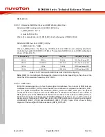
6.20.4 Basic Configuration
DMIC module must be enabled with normal operate configuration due to VAD analyses the PCM
data that from DMIC channel 0.
6.20.5 Functional Description
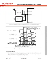
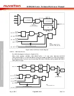
6.20.5.1 VAD Clock Control
The VAD clock control diagram is shown in Figure 6.20-2.
When VAD enabled (VADEN (VAD_SINCCTL[31] = 1) and voice detected (ACTIVE
(VAD_STATUS0[31]) = 1), the first channel of DMIC will be automatically enabled (DMIC_CTL[3:0]
= 1) and the DMIC bus clock (DMIC_CLK) will switch from the VAD path to the DMIC path.
To switch back to the VAD path again, user needs to disable the channels of DMIC (DMIC_CTL[3:0]
= 0) and clear VAD active flag and set VAD path switch by set register ACTCL (VAD_SINCCTL[30])
and SW (VAD_SINCCTL[29]) to 1.


