ISD94100 Series Technical Reference Manual
Sep 9, 2019
Page
899
of 928
Rev1.09
IS
D
9
410
0
S
ER
IE
S
T
E
C
HN
ICA
L
RE
F
E
RE
NCE
M
AN
U
AL
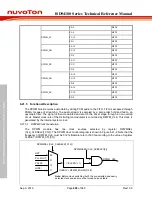
Figure 6.21-2 DPWM Clock Control Diagram
6.21.5.2 Determining Sample Rate
The sample rate at which the DPWM block consumes audio data is given by:
Fs = F_DPWM_CLK / ( ZOHDIV * K)
K = 125, if CLKSET(DPWM_CTL[31]) is 1.
K = 128, if CLKSET(DPWM_CTL[31]) is 0.
Where F_DPWM_CLK is the frequency of DPWM_CLK.
6.21.5.3 BIQ Coefficient Operation and Generation
A coefficient programmable 10 band Biquad filter (20
th
-Order IIR filter) is available.
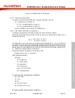
Each band biquad filter has the transfer function as H(z) and is implemented in Direct Form II
Transpose structure as.
𝐻𝐻
(
𝑧𝑧
) =
𝑏𝑏
0
+
𝑏𝑏
1
𝑧𝑧
−1
+
𝑏𝑏
2
𝑧𝑧
−2
1 +
𝑎𝑎
1
𝑧𝑧
−1
+
𝑎𝑎
2
𝑧𝑧
−2
The biquad filter in each band has 5 user programmable coefficients (b0, b1 , b2, a1 and a2) and
each band occupy 5 consecutive registers. The coefficient supports the single floating point and
fixed point. If it is fixed point CPU write DPWM_FIFO[23:0] 24 bits format 3.21. If it is the single
floating poing CPU write DPWM_FIFO[31:0] 32 bits. Set COEFFFLTEN (DPWM_COEFFCTL[1])
to 1, internal automatically transfer it to fixed point.
Fixed point Coefficient transferation from decimal to Hex:
[b0,b1,b2,a1,a2] * 2^21 --
24 bits hex
Fiflter mathmetical equation:
Parameter:
Fs = sample rate
Fc = center Splitter
Q = qualty factor
TK = tan(pi*Fc/Fs);
norm = 1/(1+TK/Q+TK^2)
G = 10^(peakgain/20)
A. Second order low pass filter coefficient
b0 = TK^2 *norm
b1 = 2 *b0
b2 = b0
a1 = 2*(TK^2-1)*norm
a2 = (1-TK/Q +TK^2) * norm
B. Second order high pass filter coefficient

