Defender 500 |
9
www.natvac.com | 800.253.5500
• The pump must be installed so that it is easily accessible for
inspection and maintenance�
• The vacuum pump must be installed on a rigid base or stand� The
drive can be by shaft, belts and pulley, or hydraulic motor�
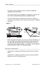
• The drive shaft must be mounted so that it does not create any
axial thrust; the inclination of the shaft must not exceed 15 degrees
(see fig. 2)
• When using belts and pulley, the pulley can be mounted directly on
the rotor shaft on the larger diameter inboard portion of the shaft�
The alignment between the pulley of the pump and the driving
pulley must be thoroughly checked� The tension must be adjusted
so the belts flex for about 1/16
th
between pulleys�
• The direction of rotation and RPM are marked on the front of the
pump�
• The direction of rotation required by your drive system should be
determined prior to ordering the pump�
Drive System ______________________________________________________
Direction of Rotation ___________________________________________
7
4. Installation
4.1 Checking at arrival
- upon receipt check that the pump and related accessories are
not damaged.
4.2 Pump mounting / Drive connection
- The pump must be installed so that it is easely accessible for
inspection and maintenance.
- The vacuum pump must be installed on a rigid base or stand.
The drive can be by cardan shaft, belts and pulley or by hydraulic
motor.
- The cardan shaft must be mounted so that it does not create any
axial thrust; the inclination of the shaft must not exceed 15
°
(see
fig. 2).
- When using the belts and pulley, the pulley can be mounted
directly on the rotor shaft eccept for R 430 .
For model R 430 pumps the pulley must be mounted with the
suitable support, supplied by JUROP.
The alignment between the pulley of the pump and the driving
pulley must be thoroughly checked.
The V-belts tension must be normal, that means the belts must
flex for about 2 cm. under the thumb pressure.
- With the hydraulic transmission the motor must be connected by
means of a support and a flexible joint.
The transmission must be protected according
to current safety standards (for Europe 89/
392 CEE standards).
Check that the actual shaft rotation
direction matches that of the arrow on
the label fixed on the front of the pump.
Fig. 2
15
°
Transmission drive
Vacuum pump axle
axles must be parallel
16 - 20 mm
Flange must be
perfectly parallel
V-belts must be
exactly in line
- Check that the rotor/shaft is not blocked.
Figure 2


