Operation
©2022 nVent
89217391 Rev. A
79
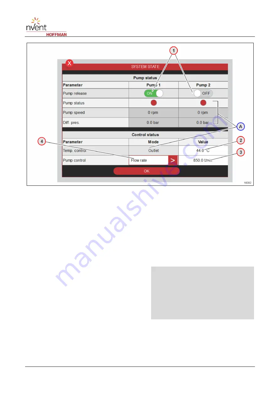
Fig. 38: Page 2300 "Schematic system diagram/System status" (example)
1
Button for configuring the pump release.
•
ON: Enabled. The pump will start if all the
process-relevant conditions are fulfilled.
•
OFF: Disabled (e.g. to deactivate the pump for a
filter change).
2
Configuration of the temperature setpoint *) **)
3
Field for adjusting the pressure/flow rate. The
display depends on the pump control type.
4
Button for selecting the pump control type *) ***)
•
based on the differential pressure of the pump
(differential pump pressure),
•
based on the differential pressure of the system
(differential system pressure),
•
based on the temperature difference
(temperature difference),
•
based on the flow rate.
A
Status indicators of the pumps:
•
Red: Component error
•
Green: Component active
•
Grey: Component OFF
•
Indication of process-relevant values
(e.g. pump speed, differential pressure)
•
Temperature control *)
-
Temperature control mode: e.g. via
the medium outlet, medium inlet
NOTE
*) See also
page 7583
for information about
the setting procedure.
**) Tapping the button will open a window for
performing the settings. Tap Enter to confirm
or ESC to cancel the action.
***) Tapping the button will open a window for
performing the settings. Select the
parameter. Then, the window closes.


