


General Information
1
nVent.com
|
3
TAblE 1: MI HEATING CAblE CONFIGURATION
XMI-L
cable
design
Heated length
End Termination
Hot/cold joint
Hot/cold joint
Hot/cold joint
Cold lead length
Heated
length
Cold lead
length
Cold lead
length
Number of
conductors
Configuration
Dual conductor
(XMI-L32 &
XMI-L62 series)
Dual conductor
(XMI-L32 &
XMI-L62 series)
D
E
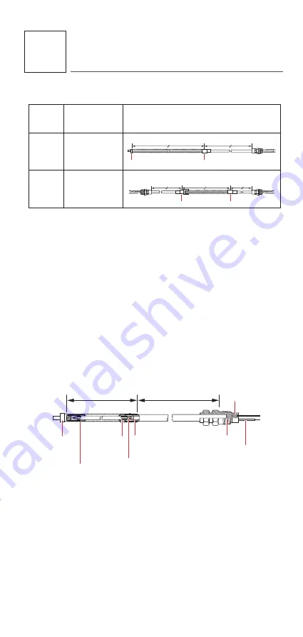
A sectional view of a Design D XMI-L heating
cable is shown in Figure 1. All of the cables include
both a heated section and a non-heating cold lead
section. These sections are joined at the hot-cold
joint where the heating element is spliced into larger
bus wires. A final transition at the end of the cold
lead section provides an environmental seal and tails
for the electrical connection. At the opposite end
of the cable, the conductors of Design D cables are
joined and hermetically sealed within an end cap.
The entire heated section of the cable is then
enclosed in a hermetically sealed flexible corrugated
conduit sheath.
Pot
Tails
(standard length
12" (30 cm))
Bus wires
Gland
connector
Hot/cold
joint
Cold lead
Heated section
Heating
element
End
Termination
Corrugate
Figure 1:
Sectional view of Design D XMI-l cable


