background image


Date: 2022/05/16 

Page

: 19 of 25


3.2  Emergency Stop Input and Output 

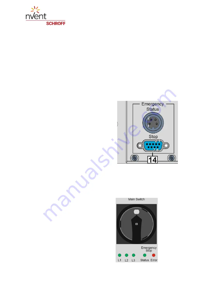
An additional emergency stop push button can be connected to the system at the 

"Emergency Stop" input (14). 

If no additional emergency stop switch is connected, the socket must be terminated with a 

jumper plug. (Scope of delivery) 

The "Emergency Status" connector can be used to transfer status signals to other devices. 

The Emergency Status plug connector a relay output of the status of the safety relay. If the 

AC and DC outputs are enabled, the relay output (pin 1+2) is closed. If the emergency stop 

function is triggered, the safety relay interrupts the relay contact. 

If the outputs are not enabled via the Output ON/OFF switch, the relay output is permanently 

open. 


Emergency Stop (DSUB9) 


Pin 1&6 

Emergency stop input circuit 1 

Pin 2&7 

Emergency stop input circuit 2 


Emergency Status (Lumberg KFV 40) 

Pin 1&2 

Relay output status safety relay 

Max. voltage = 24 VDC or 24 VAC 

Max. current = 4 A 


3.2.1 Emergency Stop Status LEDs 

The emergency stop system is powered by a 

dedicated power supply. The presence of the 

supply voltage for the emergency stop system 

is signaled by the green 

“Power” LED. 


The red 

“Error” LED signals if one of the power 

contactors got stuck 


Summary of Contents for 21270-001

Page 1: ...1 Rack Safety Plus 3 U 230 400 V AC Power Distribution Unit with Emergency Stop User Manual Release 1 4 16 05 2022 Doc No 63972 416...

Page 2: ...ility or liability for any errors or inaccuracies that may appear in this document Except as permitted by such license no part of this publication may be reproduced stored in a retrieval system or tra...

Page 3: ...on 8 2 2 Front and Rear View 9 2 3 Example Configurations 10 2 4 Mains inlets 13 2 5 AC Outlets 14 2 6 DC Outlet Option 15 2 7 RCD and Circuit Breakers 15 2 8 Surge Arrester Option 16 2 9 Inrush Curre...

Page 4: ...Date 2022 05 16 Page 4 of 25 7 Technical data 24 7 1 Dimensions 25...

Page 5: ...l environment or for commercial use 1 2 Not intended use The use of the power distribution unit as a safety function for a machine is not allowed and can lead to hazards If the equipment is used in a...

Page 6: ...Short description of the danger The signal word DANGER indicates an immediate danger Non observance will result in severe injuries or death WARNING Symbol Short description of the danger The signal wo...

Page 7: ...tive equipment at all you could be seriously injured Wear protective equipment adapted to the work processes Check the protective equipment before each use to ensure that it is intact Use only approve...

Page 8: ...Mains fuses Circuit breaker panel Emergency stop system Status LEDs for phase presence and emergency stop ON OFF switch for switched outputs Possible configuration options Mains input 400 V 3 phase or...

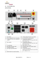
Page 9: ...1 Example Switched Power Outputs IEC 60320 C13 230 V AC 10 A 4 RCD option 13 Configurable output panel 2 Example Switched Power Outputs IEC 60320 C19 230 V AC 16 A 5 Circuit Breakers 14 Mains Fuses T...

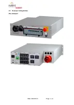
Page 10: ...Date 2022 05 16 Page 10 of 25 2 3 Example Configurations PN 21700 001...

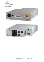
Page 11: ...Date 2022 05 16 Page 11 of 25 PN 21700 003...

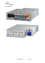
Page 12: ...Date 2022 05 16 Page 12 of 25 PN 21700 005...

Page 13: ...stribution Unit The following overview represents the availability at the time of publication of this manual For the current availability visit schroff nvent com 400 V AC Inputs Cable 2 5 m Harting Ha...

Page 14: ...the time of publication of this manual For the current availability visit schroff nvent com Switched 230 V AC Outlets IEC 60320 C13 IEC 60320 C13 IEC 60320 C13 locking outlets IEC 60320 C19locking ou...

Page 15: ...828249 The DC PSU is connected to Phase L1 2 7 RCD and Circuit Breakers The outputs are protected by circuit breakers 5 The number of the circuit breaker corresponds to the number of the output for ex...

Page 16: ...Date 2022 05 16 Page 16 of 25 2 8 Surge Arrester Option The Power Distribution Unit can be equipped with a surge arrester 1 phase 3 phase...

Page 17: ...s the current limiting circuit of the inrush current limiter will be bypassed Then the load is directly connected to the AC If an AC dump overshoots the defined time Toff it will be detected by the in...

Page 18: ...ttons The emergency stop push button is vandalism proof If the emergency stop is sheared off during operation the emergency stop function is also triggered The safety relay meets the following safety...

Page 19: ...relay output pin 1 2 is closed If the emergency stop function is triggered the safety relay interrupts the relay contact If the outputs are not enabled via the Output ON OFF switch the relay output i...

Page 20: ...e voltage and current rating of the cable should be greater than the ratings marked on the product WARNING Protective earth GND connection The power distribution unit must be operated with protective...

Page 21: ...y regulations e g by authorized specialized companies or authorized departments of the company It is mandatory to mount the power distribution unit with slide rails A The power distribution unit can b...

Page 22: ...the configuration Switch the system on via the main switch 1 The AC Service outputs will be switched on Turn on the switched AC outputs 12 13 and DC output 11 with the Outputs ON OFF switch 9 The pic...

Page 23: ...ned cloth Use a dry cloth or are cloth slightly dampened with clean water or soapy water to clean the case Do not use chemical cleaning agents 6 Disposal The devices described in this manual must be r...

Page 24: ...otection fuses 16 AT H Mains supply voltage fluctuations 10 Overvoltage category II Environment Ambient temperature operation 5 40 C Ambient temperature transport storage 25 65 C Maximum operational a...

Page 25: ...Date 2022 05 16 Page 25 of 25 7 1 Dimensions...

Reviews: