background image

2  |  nVent.com

XTV, KTV

BTV, QTVR

Go to Step 4A

Go to Step 4A

Go to Step 4B

VPL

2

3

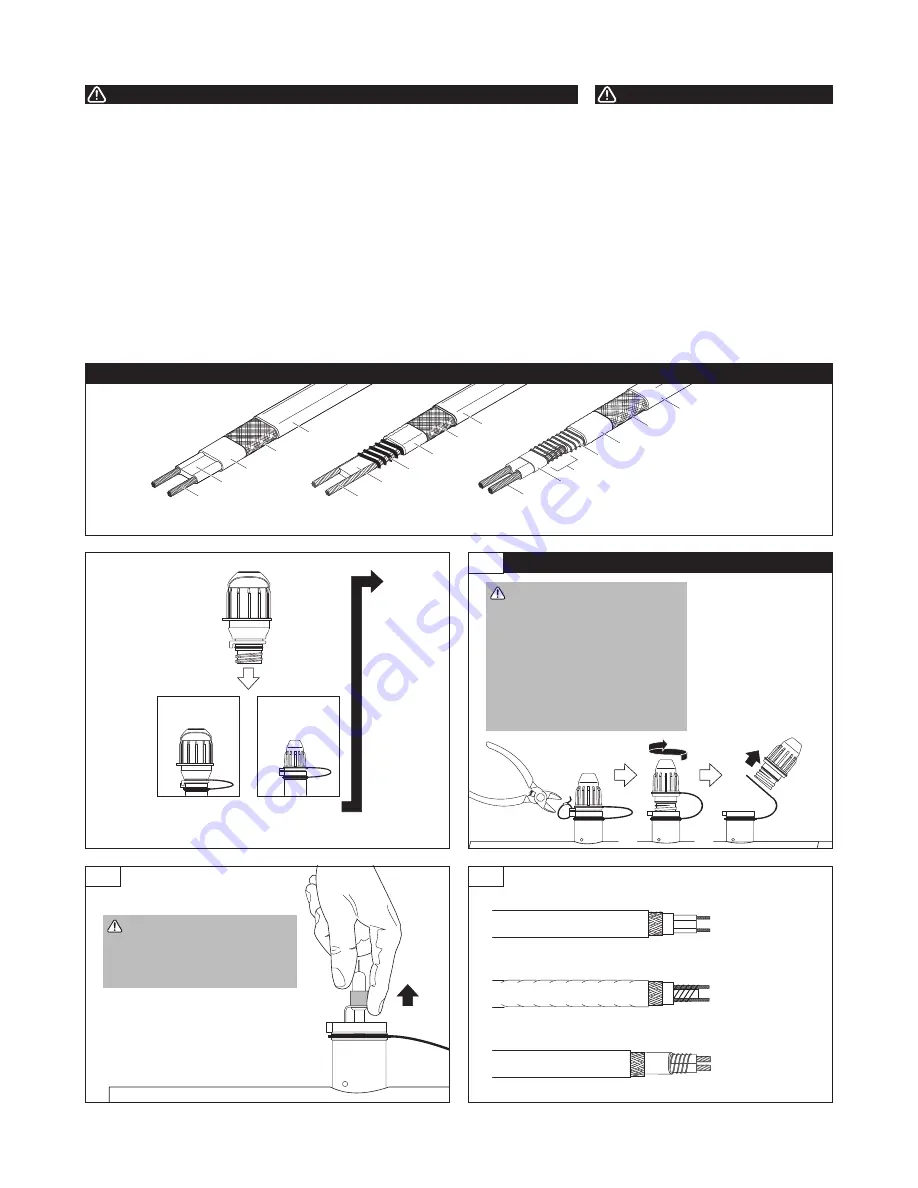
•  Remove and discard boot.
•  Using a dry towel, clean 

sealant from end of heating 

cable.

Clear jacket

Inner jacket

Braid

Outer

jacket

Heating element

Insulated bus wire

Bus wire connection

VPL-CT

Inner jacket

Outer jacket

Spacer

Conductive fiber

Bus wire

Braid

XTV-CT, KTV-CT

Bus wire

Conductive core

Inner jacket

Braid

Outer

jacket

BTV-CR, BTV-CT, QTVR-CT

HEATING CABLE TYPES

Light

Replacement

Light

Retrofit

Go to Step A

(page 6)

Go to Step 1

1

•  Turn off power.
•  Clip cable tie and 

remove.

•  Unscrew cap from 

end seal stand.

•  Remove cap from 

yellow leash.

BEGIN HERE FOR LIGHT RETROFIT. 

  WARNING: Shock Hazard. 

Electrical conductors will be 

exposed. Re-entry should 

only be performed by 

qualified  personnel. Turn off 

power and follow standard 

electrical   lockout 

procedures before opening 

end seal.

  CAUTION: Health Hazard. 

Wash hands if you contact 

sealant. Consult MSDS 

VEN 0058.

This component is an electrical device that 

must be installed correctly to ensure proper 

operation and to prevent shock or fire. Read 

these important warnings and carefully follow 

all of the installation instructions.
•  To minimize the danger of fire from 

sustained electrical arcing if the heating 

cable is damaged or improperly installed, 

and to comply with the requirements of 

nVent, agency certifications, and the National 

Electrical Code, ground-fault equipment 

protection must be used. Arcing may not be 

stopped by conventional circuit breakers.

•  Component approvals and performance are 

based on the use of nVent-specified parts 

only. Do not use substitute parts or vinyl 

 electrical  tape.

•  The black heating cable core and fibers are 

 conductive and can short. They must be 

properly  insulated and kept dry.

•  Damaged bus wires can overheat or short. 

Do not break bus wire strands when scoring 

the jacket or core.

•  Keep components and heating cable ends 

dry before and during installation.

•  Bus wires will short if they contact each 

other. Keep bus wires separated.

•  Use only fire-resistant insulation materials, 

such as fiberglass wrap or flame-retardant 

foam.

•  Leave these installation instructions with 

the user for future use.

Health Hazard: 

Prolonged or repeated contact 

with the sealant in the core sealer may 

cause skin irritation. Wash hands thoroughly. 

Overheating or burning the sealant will 

produce fumes that may cause polymer fume 

fever. Avoid contamination of cigarettes or 

tobacco. Consult MSDS VEN 0058 for further 

 information.

CHEMTREC 24-hour emergency telephone: 


(800) 424-9300.
Non-emergency health and safety information:


(800) 545-6258.

WARNING:

CAUTION:

Summary of Contents for RAYCHEM E-100-LR-A

Page 1: ...E 100 A and E 100 L A kits For technical support call nVent at 800 545 6258 TOOLS REQUIRED Wire cutters Rags or dry towel Utility knife Wire strippers Marker Needle nose pliers Panduit CT 100 crimp tool or equivalent KIT CONTENTS Item Qty Description A 1 Light assembly B 1 Core sealer for BTV QTVR XTV and KTV C 2 Insulated butt splices red D 2 Insulated parallel crimps blue E 1 Cable tie A C B E D...

Page 2: ...sustained electrical arcing if the heating cable is damaged or improperly installed and to comply with the requirements of nVent agency certifications and the National Electrical Code ground fault equipment protection must be used Arcing may not be stopped by conventional circuit breakers Component approvals and performance are based on the use of nVent specified parts only Do not use substitute p...

Page 3: ...end seal strain relief Mark heating cable jacket Lightly score jacket around and up as shown Peel off jacket Determine heating cable type and continue as shown Ensure 1 1 8 in 28 mm of heating cable is exposed above end seal strain relief The conductor should remain staggered Lightly score jacket around and up as shown Peel off jacket Unwind heating element cut and remove as shown Lightly score cl...

Page 4: ...ighten bus wires Insert bus wires into guide tubes as shown Slide core sealer onto heating cable Remove the guide tubes and dispose of them in a plastic bag CAUTION Health Hazard Wash hands if you contact sealant Consult MSDS VEN 0058 Cut and remove all fiber strands Score and remove center spacer Remove any remaining core material from bus wires If needed retwist and straighten bus wires Insert b...

Page 5: ...tall new light assembly into leash Place blue crimps onto bus wires Crimp bus wires to lead wires Push excess wire inside light Hand tighten light onto end seal stand Insert cable tie through slots on stand and light then tighten Leave these instructions with the end user for future reference Go to Page 8 ...

Page 6: ...G wire stripper to remove insulation from each of the four wire ends BEGIN HERE FOR LIGHT REPLACEMENT On existing light Cut cable tie if present Unscrew light Pull excess wire from inside light Note The existing light shown in the instructions may look different from the existing light in your installation WARNING Shock hazard Electrical conductors will be exposed Re entry should only be performed...

Page 7: ... in threads F Push excess wire inside light Hand tighten light onto end seal stand Insert cable tie through slots on stand and light then tighten Trim Weather seal G Leave these instructions with the end user for future reference Go to Page 8 ...

Page 8: ...oltage accordingly If voltage at light is present but below specified limits the light may be dim or off The following table lists typical causes for low voltages and possible solutions Cause Solution Supply voltage at start of circuit is low light is designed to work with supply voltages within 10 of nominal Increase power wire gauge size to reduce voltage drop between panel and heating cable pow...

Reviews: